Forming machining method for blind hole hollow motor shaft

A forming processing and motor shaft technology, which is applied in the field of precision transmission parts processing, can solve the problems of low material utilization rate, high machining requirements and high processing costs, and achieves the advantages of reducing processing procedures, high shape and position accuracy, and saving machining costs. Effect

Inactive Publication Date: 2021-07-09
JIANGSU PACIFIC PRECISION FORGING +1
View PDF5 Cites 6 Cited by
  • Summary
  • Abstract
  • Description
  • Claims
  • Application Information

AI Technical Summary

Problems solved by technology

At the same time, the section ratio of the tube blank used in processing is less than 55%, so when the tube blank is converted into the weight of a hollow tube with the same size, the aspect ratio of the inner hole of the hollow tube is relatively smaller, that is, the wall thickness is relatively thicker, and then, The hollow motor shaft formed by using this material has a relatively low material utilization rate
Secondly, during processing, if the hollow rotor shaft with variable diameter and multi-steps adopts the traditional process, it can only be obtained by machining a solid forging billet. This method not only wastes materials, but also has very high requirements for machining, and the overall processing cost is high. , low competitiveness

Method used


Image

  • Forming machining method for blind hole hollow motor shaft
  • Forming machining method for blind hole hollow motor shaft
  • Forming machining method for blind hole hollow motor shaft

Examples


Embodiment

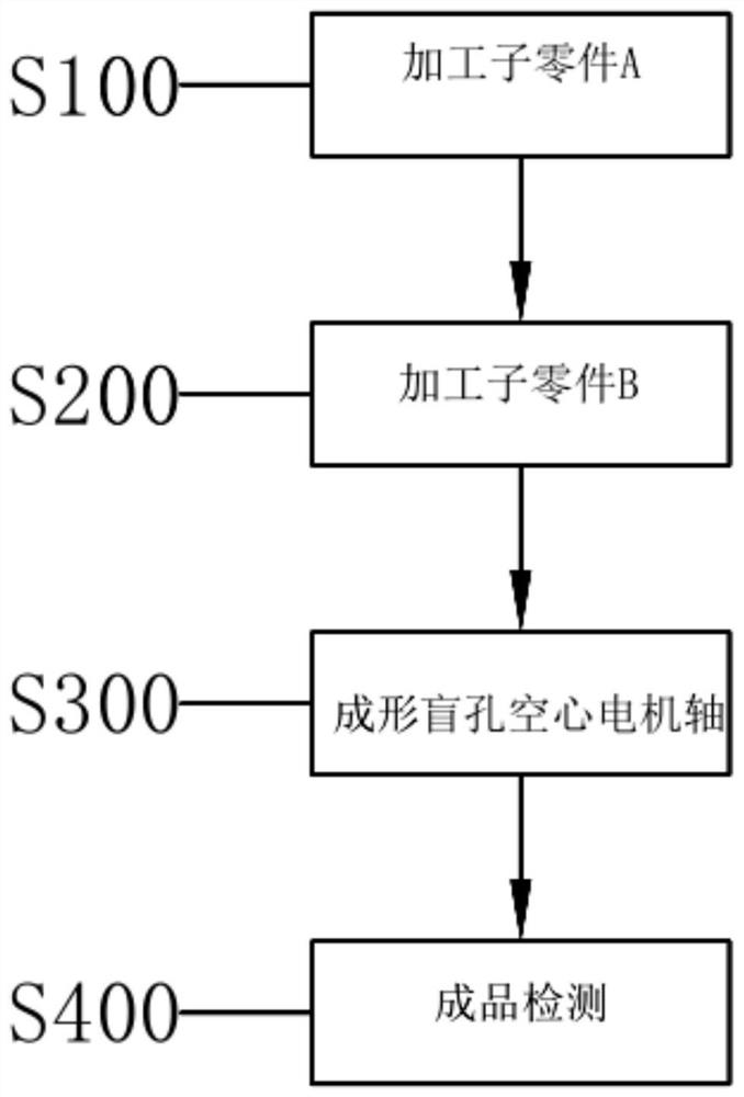
[0035] The invention provides a method for forming and processing a blind hole hollow motor shaft, see Figure 1-Figure 3 , including the following steps:

[0036] Step S100, processing sub-part A.

[0037] Step S200, processing sub-part B.

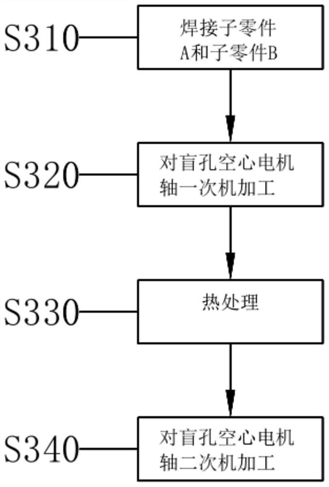
[0038] Step S300 , machining the sub-parts A and B to form a blind-hole hollow motor shaft.

[0039]During processing, sub-part A and sub-part B are processed separately first, and then the two are combined to form a blind hole hollow electronic shaft.

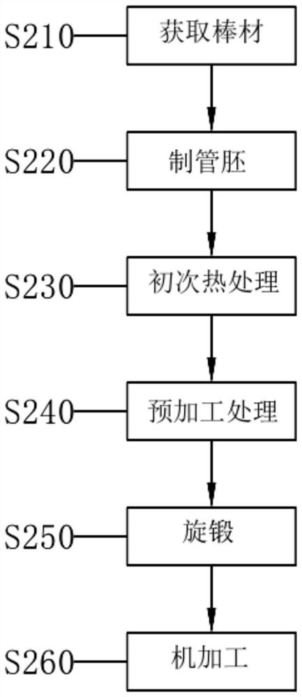
[0040] Specifically, in step S100, subpart A is one end of a blind hole hollow motor shaft without a step hole, and the step of processing subpart A includes the following steps:

[0041] S110. Raw material inspection, used to obtain materials meeting parts requirements.

[0042] S120. Cut the obtained material to obtain the length required for processing the sub-part A. When cutting, a circular saw or a band saw or other tools can be used for processing.

[0043] Step S130, processi...


PUM

PropertyMeasurementUnit
hardnessaaaaaaaaaa

Abstract

The invention relates to a forming machining method for a blind hole hollow motor shaft, and belongs to the technical field of precision transmission part machining. The forming machining method comprises the following steps that S100, a sub-part A is machined; S200, a sub-part B is machined; and S300, the sub-part A and the sub-part B are machined to form the blind hole hollow motor shaft, wherein the step (S200) of machining the sub-part B comprises the following substeps of (S210) obtaining a bar material which meets the requirements of the part; S220, the bar is made into a pipe blank; S230, the pipe blank is subjected to heat treatment, and a pipe material with the length needed by the manufactured sub-part B is obtained; S240, the outer circle of the pipe material is subjected to preprocessing treatment; S250, the pipe material is subjected to rotary swaging, and a variable-diameter multi-step sub-part B is obtained; and S260, the sub-part B is machined. By the adoption of the process method, the blind hole hollow motor shaft meeting the requirement can be machined and manufactured, the machining procedure of parts is shortened, the machining efficiency is improved, and the utilization rate of related materials and the product competitiveness are improved.

Description

technical field [0001] The invention belongs to the technical field of precision transmission parts processing, and in particular relates to a forming processing method of a hollow motor shaft. Background technique [0002] New energy electric vehicles are the current and future development direction of the automobile industry, and the development momentum is strong, but the cruising range is one of the factors restricting the development of electric vehicles. The conventional cruising range is 550 kilometers. In order to improve the cruising range, vehicle lightweight is one of the key technologies to improve the cruising range. Therefore, the motor and deceleration mechanism of the electric vehicle need to be designed with compact structure and weight reduction to reduce the weight of the vehicle. Because the torque of the shaft transmission is on the surface, major OEMs have designed hollow motor shafts. Generally, the material of the hollow shaft is carburized steel or ...

Claims


Application Information

Patent Timeline
Patent Type & Authority Applications(China)
IPC IPC(8): B23P15/14
CPCB23P15/14
Inventor 杨向东乔艳艳潘智承戴泽华蒋冬军
Owner JIANGSU PACIFIC PRECISION FORGING
Why Eureka
Try Eureka