MEMS gyroscope and preparation and packaging method thereof

A gyroscope and elastic connection technology, which is applied in the field of MEMS gyroscope and its preparation and packaging, can solve the problems of MEMS gyroscope performance degradation, sub-gyroscope resonant frequency can not achieve perfect matching, read signal error, etc., to improve the gyroscope and performance, improve accuracy and work stability, reduce the effect of offset

Active Publication Date: 2021-07-09
WUHAN UNIV
View PDF10 Cites 8 Cited by
  • Summary
  • Abstract
  • Description
  • Claims
  • Application Information

AI Technical Summary

Problems solved by technology

At present, commercial gyroscopes have the following disadvantages: 1. The coupling between sub-gyroscopes is generally connected by spring beam structure, which is a weak coupling structure
When there are processing defects and errors, the resonant frequencies between sub-gyroscopes cannot be perfectly matched, and different sub-gyroscopes respond differently to external input angular velocity signals, resulting in readout signal errors
2. At present, the number of anchor points in commercial gyroscope structures is generally greater than four. More anchor point structures make gyroscope devices vulnerable to packaging stress, which leads to a decline in the performance of MEMS gyroscopes.

Method used


Image

  • MEMS gyroscope and preparation and packaging method thereof
  • MEMS gyroscope and preparation and packaging method thereof
  • MEMS gyroscope and preparation and packaging method thereof

Examples


Embodiment 1

[0047] It should be noted that the diagrams provided in this embodiment are only schematically illustrating the basic ideas of the present invention, and only the components related to the present invention are shown in the drawings rather than the number, shape and size of components in accordance with actual implementation Drawing, the type, quantity and proportion of each component can be changed arbitrarily during its actual implementation, and the component layout type may also be more complex.

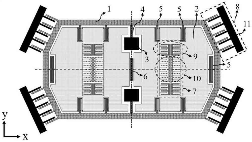
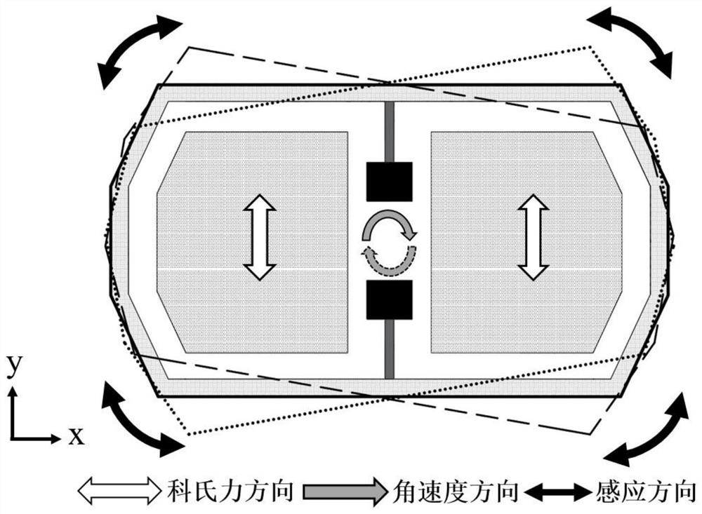
[0048] MEMS gyroscope structure planar structure of the present invention such as figure 1 As shown, the MEMS gyroscope structure of the present invention consists of a detection outer frame 1, a mass block 2, a fixed anchor point 3, a primary elastic connecting beam 4, a secondary elastic connecting beam 5, a coupling elastic connecting beam 6, a drive unit 7 and a detection unit 8 and other structures, the structure is symmetrical along the X and Y central axes.

[0049] Exce...

Embodiment 2

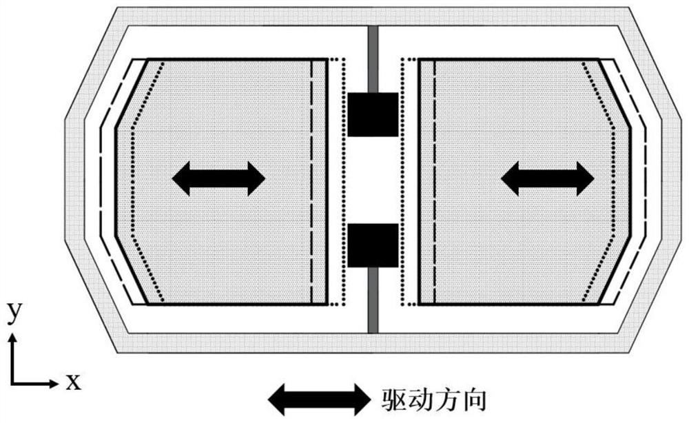
[0064] Based on the planar structure of the MEMS gyroscope in Embodiment 1, the position of its secondary elastic connecting beam 5 can be changed, and its planar structure is as follows Figure 5 shown. Different from the planar structure of Embodiment 1, the two secondary elastic connecting beams 5 located on the central axis in the X direction can be removed. At this time, full decoupling can be realized between the driving resonator structure and the detection frame 1 in the driving working mode. When the MEMS gyroscope driving resonator is in the working mode, the secondary elastic connecting beam adopts a double folded beam structure, which can minimize the interference of the driving oscillation motion of the mass block 2 on the detection outer frame 1 and the detection unit 8, which can effectively reduce the The orthogonal coupling of gyroscope drive and detection direction can significantly reduce the bias stability of MEMS gyroscope and effectively improve the perf...

Embodiment 3

[0066] Based on the planar structure of the MEMS gyroscope in Embodiment 1, the position of the driving electrodes 10 and the functional electrodes located in the driving unit 7 can be flexibly arranged, and functional electrodes such as orthogonal compensation electrodes 13 can be added in the driving unit 7, and its planar structure Such as Image 6 shown. The two orthogonal compensation electrodes 13 can be located at the inner centers of the two drive units 7 , and the orthogonal compensation electrodes 13 are comb-teeth electrodes with variable pitch, which are distributed symmetrically with twist along the central symmetry axis in the Y direction. Due to processing tolerances or material defects, the structural mass 2 may deflect in the driving direction and the central axis of the X direction. At this time, the left and right mass blocks 2 produce an asymmetric resonance working mode, and their mechanical motion errors will be transmitted through the secondary elastic c...


PUM


Abstract

The invention discloses an MEMS gyroscope and a preparation and packaging method thereof. The MEMES gyroscope is of a tuning fork type gyroscope structure and comprises an outer frame, a mass block, an anchor point, a driving unit, a detection unit, a first-stage elastic connecting beam, a second-stage elastic connecting beam and a coupling elastic connecting beam. The driving mode is in-plane reverse oscillation motion of the two mass blocks relative to the outer frame, and the sensing mode is in-plane torsional pendulum motion of the whole structure. Detected Coriolis force signals are output in a differential mode through the induction electrodes located at the four corners of the outer frame. Through the driving mass block of the MEMS gyroscope, full coupling is achieved, meanwhile, fewer anchor point structures are provided, errors caused by machining errors and packaging stress can be effectively restrained, and therefore the precision and performance of the MEMS gyroscope are improved. According to the preparation and packaging method provided by the invention, vacuum packaging of the device is realized by using a wafer level vacuum bonding method, the difficulty of device design, preparation and electrical wiring is reduced, and the method is simple and efficient.

Description

technical field [0001] The invention relates to the field of MEMS gyroscope sensor design and processing, in particular to a MEMS gyroscope and a preparation and packaging method thereof. Background technique [0002] The gyroscope is a sensing device that measures the rotation angle or angular displacement of an object. It is used to realize the measurement and control of the attitude and trajectory of the moving carrier. It is the basic core device of the inertial system. Compared with traditional mechanical and optical gyroscopes, micro-electro-mechanical system (MEMS) gyroscopes have the advantages of low cost, small size, low power consumption, and can be integrated with circuits. They are widely used in consumer electronics and medical electronics. , automotive electronics, aerospace and military and other fields. The most widely used commercial MEMS gyroscope is the tuning fork gyroscope. Its principle is the Coriolis effect. When the platform rotates, the suspended ...

Claims


Application Information

Patent Timeline
Patent Type & Authority Applications(China)
IPC IPC(8): G01C19/5621G01C19/5628
CPCG01C19/5621G01C19/5628
Inventor 吴国强吴忠烨杨尚书
Owner WUHAN UNIV
Why Eureka
Try Eureka