Ultraviolet LED and method of making the same

A production method and ultraviolet technology, applied in the direction of semiconductor devices, electrical components, circuits, etc., can solve problems such as expanding and increasing the demand for ultraviolet LEDs, and achieve improved radiation recombination efficiency, reduced quantum-confined Stark effect, and high luminescence efficiency effect

Active Publication Date: 2022-07-15
XIAMEN CHANGELIGHT CO LTD
View PDF0 Cites 0 Cited by
  • Summary
  • Abstract
  • Description
  • Claims
  • Application Information

AI Technical Summary

Problems solved by technology

In addition, due to the entry into force of the Minamata Convention, the production and import and export of mercury-containing products will be banned from 2020, restricting the production and use of traditional mercury lamps, leading to further expansion of the demand port for ultraviolet LEDs as ultraviolet light sources, further increasing the Increased people's demand for UV LEDs with high luminous efficiency

Method used


Image

  • Ultraviolet LED and method of making the same
  • Ultraviolet LED and method of making the same
  • Ultraviolet LED and method of making the same

Examples


Embodiment 1

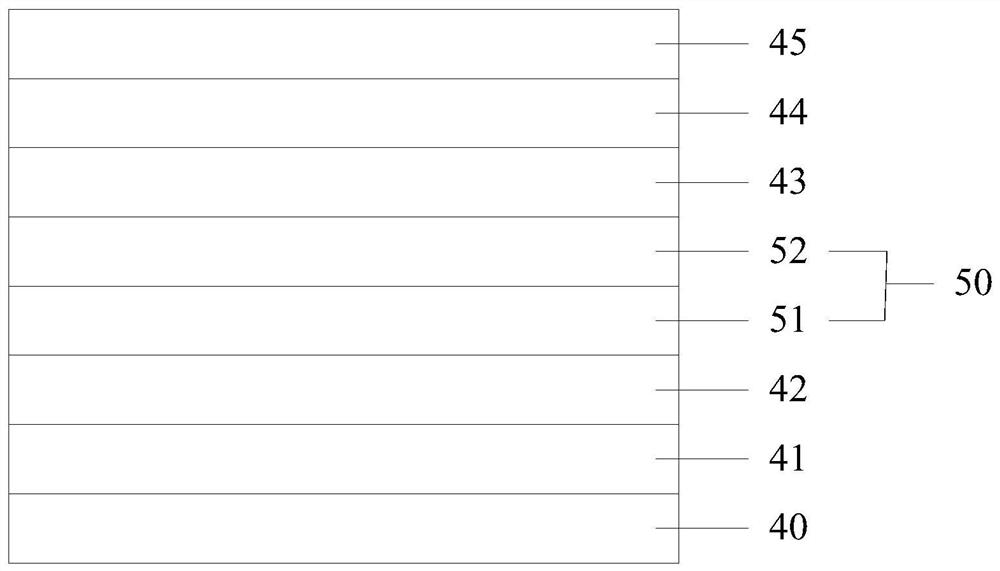
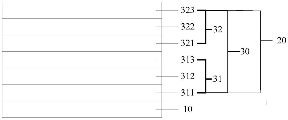
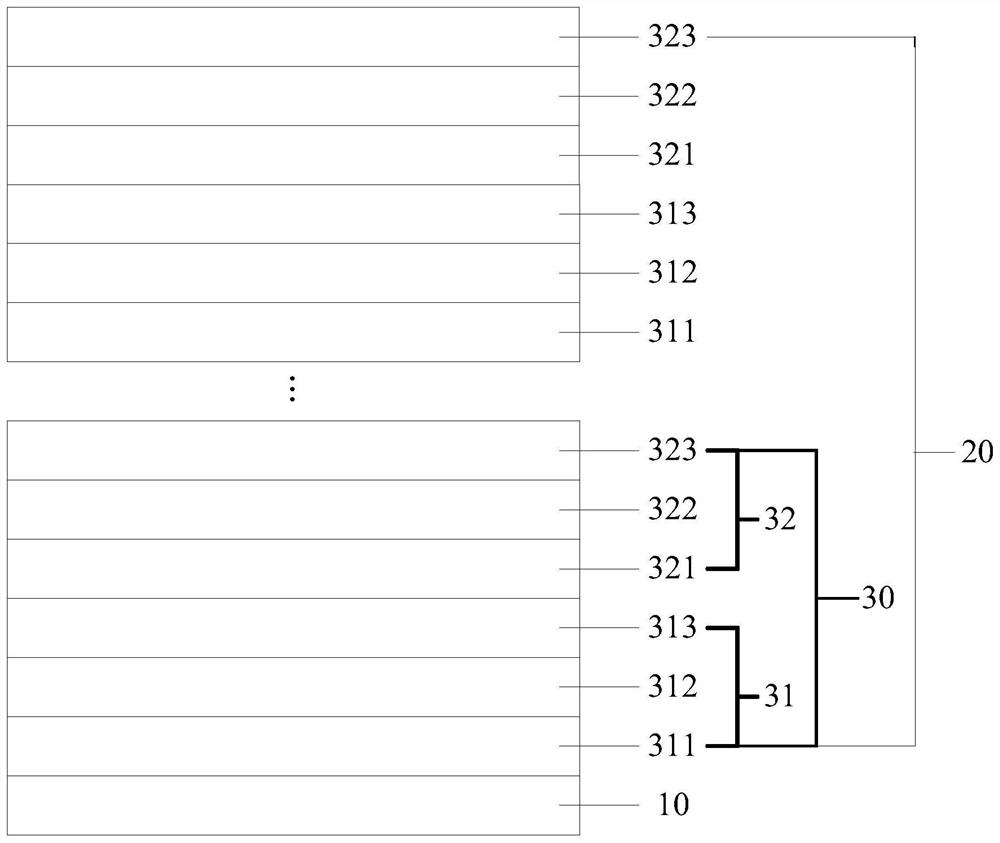
[0070] Specifically, as Figure 5 As shown, the UV LED sequentially includes: a substrate 60, an AlN buffer layer 61, an AlN / AlGaN stress release layer 62, an n-AlGaN electron supply layer 63, a light-emitting layer 70, an AlGaN blocking layer 64, and a p-AlGaN hole supply layer 65. a GaN ohmic contact layer 66, wherein the light emitting layer 70 includes 2 to 12 stacked units 71, and the first stress balance layer 712 in each of the stacked units 71 is In x Ga 1-x N stress balance layer, the second stress balance layer 715 is In x Ga 1-x N stress balance layer, the first quantum barrier layer 711 is Al a Ga 1-a N quantum barrier layer, the second quantum barrier layer 713 is Al a Ga 1-a N quantum barrier layer, the first quantum well layer 714 is Al b In c Ga 1-b-c N quantum well layer, the second quantum well layer 716 is Al b In c Ga 1-b-c N quantum well layer.

Embodiment 2

[0072] Specifically, as Image 6 As shown, the UV LED sequentially includes: a substrate 80, an AlN buffer layer 81, an AlN / AlGaN stress release layer 82, an n-AlGaN electron supply layer 83, a light-emitting layer 90, an AlGaN blocking layer 84, and a p-AlGaN hole supply layer 85. , GaN ohmic contact layer 86, wherein the light emitting layer 90 includes 2 to 12 stacked units 91, and the first stress balance layer 912 in each of the stacked units 91 is a GaN stress balance layer, and the second stress balance layer 915 is a GaN stress balance layer, and the first quantum barrier layer 911 is Al a Ga 1-a N quantum barrier layer, the second quantum barrier layer 913 is Al a Ga 1-a N quantum barrier layer, the first quantum well layer 914 is Al b In c Ga 1-b-c N quantum well layer, the second quantum well layer 916 is Al b In c Ga 1-b-c N quantum well layer.

[0073]It should be noted that, in the ultraviolet LEDs provided in the first and second embodiments, the latti...


PUM


Abstract

The embodiment of the present application discloses an ultraviolet LED and a manufacturing method thereof. The ultraviolet LED includes: a substrate and a light-emitting layer, wherein the light-emitting layer includes at least one stacking unit, and the stacking unit includes a quantum barrier unit and a quantum well unit, and the The quantum barrier unit includes a stacked first quantum barrier layer, a first stress balance layer, and a second quantum barrier layer, and the quantum well unit includes a stacked first quantum well layer, a second stress balance layer, and a second quantum well layer; Wherein, the lattice constant of the first stress balance layer is greater than the lattice constant of the first quantum barrier layer and the second quantum barrier layer, and the lattice constant of the second stress balance layer is greater than that of the first quantum barrier layer The lattice constants of the quantum well layer and the second quantum well layer can balance the compressive stress of the second quantum barrier layer under the first quantum well layer to the first quantum well layer, and reduce the The quantum confinement Stark effect in the first quantum well layer improves the luminous efficiency of the ultraviolet LED.

Description

technical field [0001] The present application relates to the field of LED technology, and in particular, to an ultraviolet LED and a manufacturing method thereof. Background technique [0002] At the beginning of the 21st century, with the development of LED solid-state light source technology, ultraviolet LED (UV LED) entered the era of LED lighting and became a very important ultraviolet light source. Compared with traditional gas ultraviolet light sources such as mercury lamps and xenon lamps, ultraviolet LEDs have ultra-long life, cold light source, no thermal radiation, life is not affected by switching times, high energy, uniform irradiation, high efficiency, no toxic substances, and environmental protection. And the powerful advantages of realizing the miniaturization of equipment, make people have a strong interest in the technology research and development of ultraviolet LEDs, and promote the rapid development of ultraviolet LEDs. [0003] Moreover, with the devel...

Claims


Application Information

Patent Timeline
Patent Type & Authority Patents(China)
IPC IPC(8): H01L33/06H01L33/12H01L33/00
CPCH01L33/06H01L33/12H01L33/0075
Inventor 卓祥景万志程伟尧刚林志伟
Owner XIAMEN CHANGELIGHT CO LTD
Why Eureka
Try Eureka