Semiconductor laser for 50: 50 split optical fiber coupling output, and method

A fiber coupling and semiconductor technology, applied in the field of lasers, can solve the problems that the position deviation of the coupler is easy to affect the coupling efficiency and the beam quality, and limit the application, so as to improve the accuracy of data, increase the stability and reliability, and optimize the coupling efficiency. Effect

Pending Publication Date: 2021-07-23
THE FIRST RES INST OF MIN OF PUBLIC SECURITY +1
0 Cites 0 Cited by

AI-Extracted Technical Summary

Problems solved by technology

Among them, the pluggable fiber optic coupler is easy to operate and the fiber can be replaced, but the position deviation of the coupler (including the distance between the fiber end face and the focal point,...

Method used

Further, in said method, utilize optical fiber three-dimensional adjustment structure 9 to control the relative position and angle of the laser spo...

Abstract

The invention discloses a semiconductor laser for 50: 50 split optical fiber coupling output and a method. According to the invention, an included angle between the center line of the transmitting end of a pumping laser generator and the end face of a semiconductor gain chip is 45 degrees, and a focusing lens is located between the transmitting end of the pumping laser generator and the semiconductor gain chip; an output coupling mirror is opposite to an output window area of the semiconductor gain chip, a frequency doubling crystal is located on a reflection light path of the output coupling mirror, and an end mirror is opposite to an emergent end of the frequency doubling crystal; a coupling lens is positioned between the emergent end of the output coupling mirror and the input end of a split optical fiber; and the input end of the split optical fiber is connected with a first output end of the split optical fiber and a second output end of the split optical fiber through an optical fiber splitter. According to the invention, intensity calibration can be carried out in a fluorescence spectrum and a Raman spectrum of genetic spectroscopy analysis, data accuracy is improved, and the complexity of a spatial spectroscopic optical path of a test system is simplified.

Application Domain

Technology Topic

Image

  • Semiconductor laser for 50: 50 split optical fiber coupling output, and method
  • Semiconductor laser for 50: 50 split optical fiber coupling output, and method

Examples

  • Experimental program(2)

Example Embodiment

[0023] Example 1
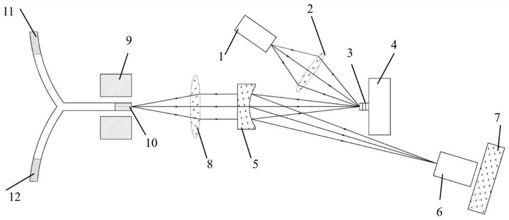
[0024] This embodiment provides a 50:50 split-fiber coupled output semiconductor laser, such as figure 1 As shown, it includes pump laser generator 1, focusing lens 2, semiconductor gain chip 3, output coupling mirror 5, frequency doubling crystal 6, end mirror 7, coupling lens 8, splitting fiber input port 10, splitting fiber output port One 11 and splitting fiber output end two 12; the included angle between the midline of the emission end of the pump laser generator 1 and the end face of the semiconductor gain chip 3 is 45°, and the focusing lens 2 is located at the pump laser generator 1 between the transmitting end of the semiconductor gain chip 3 and the output coupling mirror 5; On the way, the frequency doubling crystal 6 is located between the end mirror 7 and the output coupling mirror 5; the coupling lens 8 is located on the transmission optical path of the output coupling mirror 5, and the splitting fiber input end 10 is opposite to the output end of the coupling lens 8; The input end 10 of the splitting fiber is respectively connected to the first output end 11 of the splitting fiber and the second output end 12 of the splitting fiber through a fiber splitter.
[0025] Further, the output coupling mirror 5 reflects laser light with a wavelength of 1010 nm and enhances the reflection of laser light with a wavelength of 505 nm, and the end mirror 7 reflects laser light with a wavelength of 1010 nm and laser light with a wavelength of 505 nm.
[0026] Furthermore, the output coupling mirror 5 has a reflectivity of >99.9% for the laser with a wavelength of 1010nm, and the reflectivity of the end mirror 7 for the laser with a wavelength of 1010nm and the laser with a wavelength of 505nm is >99.9%.
[0027] Further, in the above-mentioned semiconductor laser, the input end 10 of the splitting fiber is fixed on the three-dimensional fiber adjustment structure 9 .
[0028] Further, the semiconductor gain chip 3 is fixed on the thermally deposited copper sheet 4 . The heat-deposited copper sheet 4 is used for temperature control of the semiconductor gain chip 3 and at the same time for eliminating the thermal lens effect and improving the stability of the output power of the laser.
[0029] Further, in this embodiment, as figure 2 As shown, the semiconductor gain chip 3 includes an output window area 13, a gain area 14, and a high reflection mirror area 15 in sequence; the output window area 13 is composed of 3λ/2 AlGaAs; the gain area 14 is composed of a plurality of InGaAs/GaAsP/AlGaAs It is composed of strain-compensated quantum wells, and the quantum period of the gain region is λ/2, which constitutes the duty cycle gain in order to obtain the maximum laser gain; the high reflection mirror region 15 is alternately grown by 30.5 AlGaAs and GaAs whose optical thickness is λ/2 Its reflectivity is as high as 99.9%.

Example Embodiment

[0030] Example 2
[0031] This embodiment provides a working method of the semiconductor laser described in Embodiment 1, and the specific process is:
[0032] The pump laser generator 1 emits laser light with a wavelength of 808nm, which is converged by the focusing lens 2 and focused at 45° on the semiconductor gain chip 3, and the semiconductor gain chip 3 generates laser light with a wavelength of 1010nm.
[0033] It should be noted that, because the end face of the semiconductor gain chip 3 has a highly reflective mirror region (Bragg reflector structure), the reflectivity to laser light with a wavelength of 1010nm is greater than 99.9%, and forms a 1010nm resonant cavity with its output window region, so the output wavelength of 1010nm laser.
[0034]The 1010nm laser light is reflected by the output coupling mirror 5 and converged onto the frequency doubling crystal 6, and the laser light with a wavelength of 505nm is generated by the frequency doubling effect of the frequency doubling crystal 6. The end mirror 7 has a high reflectivity (>99.9%) for the laser with a wavelength of 1010nm and the laser with a wavelength of 505nm. The mirror 5 and the end mirror 7 form a laser oscillation cavity with a wavelength of 1010nm. The laser with a wavelength of 1010nm is continuously converted into a 505nm laser in the oscillation cavity, and the 505nm laser that reaches the end mirror 7 through the frequency doubling crystal 6 is also reflected and then passes through the output coupling mirror. 5 output;
[0035] The laser with a wavelength of 505nm is output through the output coupling mirror 5, and the focal length is converged to the splitting fiber input end 10 by the coupling lens 8, and then transmitted to the splitting fiber output end 11 and The output end 12 of the splitting fiber forms a 505nm laser output with uniform energy and stability at the output end 11 of the splitting fiber and the second output end 12 of the splitting fiber.
[0036] Further, in the above method, the optical fiber three-dimensional adjustment structure 9 is used to control the relative position and angle of the laser spot after the beam splitting optical fiber input end 10 and the coupling lens 8 focus, so as to realize the control of coupling efficiency and output beam quality.
[0037] Further, in the above method, it should be noted that after the light energy emitted by the pump laser generator 1 is converged by the focusing lens 2, it is absorbed by the output window region 13 made of AlGaAs to generate photogenerated carriers, that is, electron-hole pairs . Electron-hole pairs will diffuse to the conduction band and valence band of the gain region 14 composed of InGaAs/GaAsP/AlGaAs quantum wells, and the number of excitons will be reversed, thereby generating spontaneous emission of 1010nm near-infrared light; because AlGaAs and GaAs alternate The grown high reflective mirror region 15 has a reflectivity of 99.9% to 1010nm wavelength, so the 1010nm light of stimulated radiation is reflected by the highly reflective mirror region 15 . Because the quantum wells are located at the antinodes of the standing wave of the laser, the optical cavity oscillates and the radiation is amplified, and the 1010nm laser is finally emitted through the output window region 13 and then focused by the output coupling mirror 5 .

PUM

no PUM

Description & Claims & Application Information

We can also present the details of the Description, Claims and Application information to help users get a comprehensive understanding of the technical details of the patent, such as background art, summary of invention, brief description of drawings, description of embodiments, and other original content. On the other hand, users can also determine the specific scope of protection of the technology through the list of claims; as well as understand the changes in the life cycle of the technology with the presentation of the patent timeline. Login to view more.

Similar technology patents

Classification and recommendation of technical efficacy words

  • High beam quality
  • Improve coupling efficiency

Semiconductor laser

InactiveUS20080089374A1High beam qualityImproved electrical propertyOptical wave guidanceLaser detailsPhysicsOptoelectronics
Owner:OSRAM OPTO SEMICON GMBH & CO OHG

Full solid state picosecond laser regenerative amplifier

Owner:INST OF PHYSICS - CHINESE ACAD OF SCI +1

High-efficiency compact end surface pumping lath laser amplifier apparatus

Owner:TECHNICAL INST OF PHYSICS & CHEMISTRY - CHINESE ACAD OF SCI

Silicon carbide crystal growth apparatus

Owner:北京天科合达新材料有限公司 +1

Coupling light element

Owner:IND TECH RES INST
Why Eureka
Try Eureka