
Solid waste treatment incineration device convenient to operate

An incineration device and an easy-to-operate technology, applied in incinerators, combustion methods, combustion types, etc., can solve the problems of waste of carbon monoxide fuel resources, insufficient straw incineration, etc. Effect

Pending Publication Date: 2021-07-27
辽宁兴东科技有限公司
View PDF0 Cites 0 Cited by
  • Summary
  • Abstract
  • Description
  • Claims
  • Application Information

AI Technical Summary

Problems solved by technology

[0006] The purpose of the present invention is to solve the problems of insufficient straw burning and waste of carbon monoxide fuel resources, and propose an easy-to-operate solid waste treatment and incineration device

Method used


Image

  • Solid waste treatment incineration device convenient to operate
  • Solid waste treatment incineration device convenient to operate
  • Solid waste treatment incineration device convenient to operate

Examples


Embodiment 1

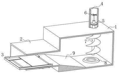
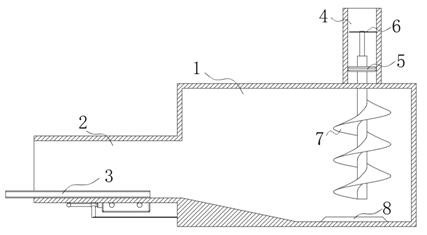
[0028] refer to Figure 1-6 , an easy-to-operate solid waste treatment and incineration device, comprising a combustion furnace 1 body, an igniter 8 and an external carbon monoxide collection device. Exhaust pipe 4 for exhaust, so that the gas generated by combustion can be effectively discharged, avoiding excessive gas accumulation in the combustion furnace 1, and at the same time avoiding exhaust gas from being discharged from the push box 2, so that the exhaust gas and air will form convection, which will not It is beneficial for oxygen to enter the pushing box 2 so that the combustion reaction is interrupted.

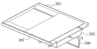
[0029] The pushing box 2 is provided with a propulsion device 3 for advancing the packed straw block, referring to Figure 3-4 Shown, propulsion device 3 comprises double rail 301, baffle plate 302, gas tank 305, placement plate 307 and push rod mechanism, and double rail 301 is arranged on the edge of inner wall bottom of pushing box 2, and baffle plate 302 is arr...

Embodiment 2

[0039] refer to Figure 1-2 As shown, the exhaust pipe 4 is provided with a straw crushing device. The straw crushing device includes a carbon dioxide absorbing disc 5, a fan blade 6 and a screw knife 7. The carbon dioxide absorbing disc 5 is fastened to the inner wall of the exhaust pipe 4, and the carbon dioxide absorbing disc 5 is filled with calcium oxide for absorbing carbon dioxide, which can effectively absorb carbon dioxide in the exhaust gas, and at the same time filter and leave carbon monoxide, and fill the carbon monoxide into the gas storage tank 305 through the carbon monoxide collection device.

[0040] The spiral knife 7 is interspersed on the axis of the carbon dioxide absorbing disk 5, the fan blade 6 is arranged on the top of the spiral knife 7, and the spiral knife 7 rotates downward, and the exhaust gas can drive the fan blade 6 on the top of the spiral knife 7 to rotate, and then drive the spiral knife 7 to rotate, This facilitates the crushing of the sta...


PUM


Abstract

The invention discloses a solid waste treatment incineration device convenient to operate. The solid waste treatment incineration device comprises a combustion furnace body, an igniter and an external carbon monoxide collecting device; and a pushing box used for transporting straw blocks is arranged on the side wall of the combustion furnace, an exhaust pipe used for exhausting is arranged at the top of the combustion furnace, and a straw block crushing device is arranged in the exhaust pipe. According to the solid waste treatment incineration device, discharged carbon monoxide gas outlets are distributed in the slope, a large amount of high-speed carbon monoxide rushes into the straw blocks, the packaged straw blocks can be scattered through flushing, the straw blocks are rapidly scattered, the gas is carbon monoxide, the ignition effect can be achieved, and complete combustion of straw can be accelerated; and fan blades are arranged at the top of a spiral cutter, the spiral cutter rotates downwards, waste gas can drive the fan blades at the top of the spiral cutter to rotate, then the spiral cutter is driven to rotate, the straw blocks can be crushed conveniently, and sufficient combustion of straw is facilitated.

Description

technical field [0001] The invention relates to the technical field of solid waste treatment, in particular to an incineration device for solid waste treatment with convenient operation. Background technique [0002] At present, a large amount of straw waste will be produced in the process of agricultural production and planting. These straw wastes are usually used as livestock feed or burned to make plant ash and returned to the field, which is conducive to the development of agriculture and animal husbandry. However, the existing straw burning process usually There are the following problems: [0003] First of all, the incineration of straw is not sufficient. The main reason for this is that when the straw is packed and put into the incinerator, because the straw is compacted, it is difficult for the flame to reach the inside of the straw bag during the incineration process, which will cause insufficient combustion. It is very easy to cause too much straw in the plant ash...

Claims


Application Information

Patent Timeline
IPC IPC(8): F23G5/033F23G5/12F23G5/44
CPCF23G5/033F23G5/12F23G5/44F23G5/444F23G2201/80F23G2204/103F23G2205/20
Inventor 都基辉孙庆明刘志勇马瑞新李春雨张欢都兴东杨瑞丰
Owner 辽宁兴东科技有限公司
Learn More