A multi-layer multi-head spiral tube type absorption heat exchange unit

A technology of heat exchange unit and spiral heat exchange tube, which is applied in the field of multi-layer multi-head spiral tube type absorption heat exchange unit, can solve the problems of difficult structure and process, difficult processing, limited design, etc., so as to reduce the processing difficulty and cost, Reduce processing steps and difficulty, improve the effect of compact space

Active Publication Date: 2022-06-24
TSINGHUA UNIV
View PDF10 Cites 0 Cited by
  • Summary
  • Abstract
  • Description
  • Claims
  • Application Information

AI Technical Summary

Problems solved by technology

The main disadvantage of the two types of structures is that there are many vacuum sealing links of heat exchange tubes. Even for small units, a lot of welding or tube expansion work is still required, which is difficult to process, high in cost, and difficult to maintain a high vacuum. Tightness, which is the main structural and technological problem in the miniaturization of the absorption machine
[0003] Some existing miniaturized lithium bromide absorption machines also use spiral heat exchange tubes, such as the technologies disclosed in patents CN201382633Y, CN201520768946.2, and CN200920096002.X. The velocity of the water flow, the density of the liquid outside the tubes, the total area of ​​the heat exchange tubes, and the space size of the unit are mutually restricted, which requires that the arrangement of the heat exchange tubes can provide sufficient degrees of freedom. Straight tube heat exchange tubes have a low degree of freedom and limited design; secondly, due to the restriction of the existing spiral tube bending technology, the diameter of the spiral tube should not be too small, generally more than 150mm, which makes the middle of the spiral tube larger. The space cannot be effectively utilized, making the unit compact;

Method used


Image

  • A multi-layer multi-head spiral tube type absorption heat exchange unit
  • A multi-layer multi-head spiral tube type absorption heat exchange unit
  • A multi-layer multi-head spiral tube type absorption heat exchange unit

Examples


Embodiment Construction

[0028] The present invention will be further described in detail below in conjunction with the accompanying drawings.

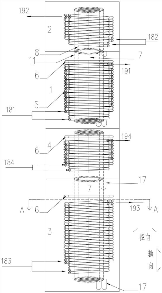
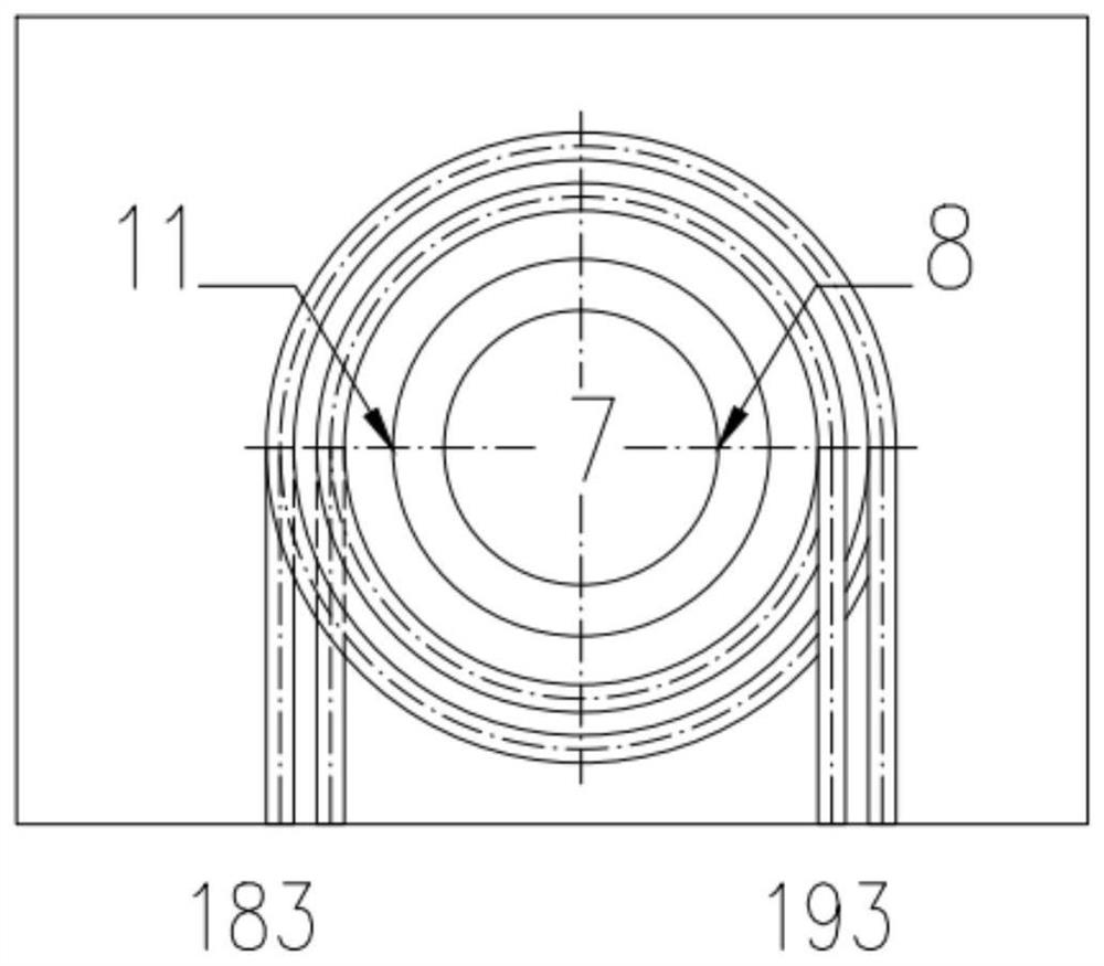
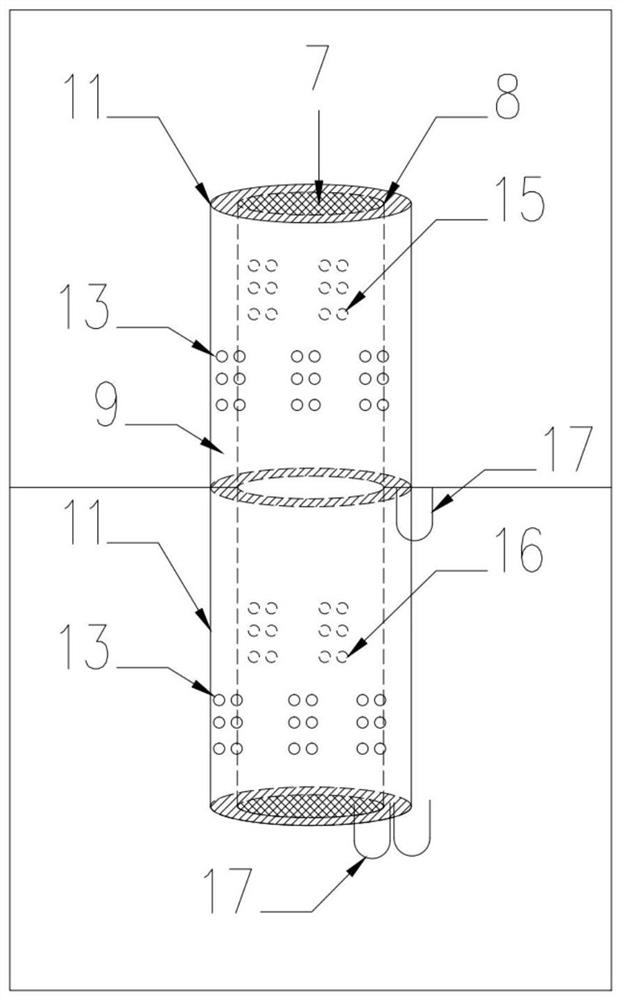
[0029] like figure 1 and figure 2 In the illustrated embodiment 1 of the present invention, the absorption heat exchange unit includes four heat exchange unit cavities: a condenser 2, a generator 1, an evaporator 4 and an absorber 3, wherein the condenser 2 is located above the generator 1, The condenser 2 and the generator 1 are connected through the central cylindrical steam channel 7, the evaporator 4 is located above the absorber 3, and the evaporator 4 and the absorber 3 are also connected through the inner cylindrical steam channel 7. Auxiliary cylinder orifice plate baffle 11 is installed outside the cylindrical steam channel 7, at least one layer of spiral heat exchange tube group 5 is arranged outside the auxiliary cylinder orifice plate baffle 11, the entrance and exit of the spiral heat exchange tube group 5 The water or cold water pipelines are...


PUM


Abstract

The invention discloses a multi-layer multi-head spiral tube type absorption heat exchange unit belonging to the field of energy saving; wherein the condenser is located above the generator, the condenser and the generator are connected through a cylindrical steam channel arranged in the center, and the evaporator Located above the absorber, the evaporator and the absorber are connected by a cylindrical steam channel inside; an auxiliary cylinder orifice baffle is installed outside the cylindrical steam channel, and at least one layer of spiral heat exchange tubes is arranged in the auxiliary cylinder Outside the orifice baffle, the inlet and outlet pipes of the spiral heat exchange tube group are fixedly connected to the shell of the absorption heat exchange unit; the liquid distribution pipes with small holes evenly opened at the upper end or lower end are installed directly above the spiral heat exchange tube group. The number of welding seams in the invention is greatly reduced, and at the same time, the welding link between each layer of the mosquito-repellent coil tube is avoided, and the vacuum airtightness is improved. There are multiple degrees of freedom in the design of the coil, and the design value of the flow rate in the tube and the density of the liquid distributed outside the tube can be met through changes in the number of groups, layers, and heads.

Description

technical field [0001] The invention belongs to the technical field of energy saving, in particular to a multi-layer multi-head spiral tube type absorption heat exchange unit. Background technique [0002] Lithium bromide absorbers are widely used in heating systems and various industrial processes. Miniaturization, compactness, cost reduction, and simplified structure are the main development directions for equipment research and development in this field. Miniaturization, ease of processing, and reduction in the need for vacuum sealing line lengths for heat exchange tubes. At present, the mainstream absorber structure of various manufacturers is mainly straight tube type, that is, long and straight heat exchange tubes are used, tube sheets are arranged at both ends, and each heat exchange tube is vacuum sealed by tube expansion technology or welding technology, so that the inner side of the tube is sealed. It is high pressure, and the outside of the tube is negative press...

Claims


Application Information

Patent Timeline
Patent Type & Authority Patents(China)
IPC IPC(8): F25B15/06
CPCF25B15/06Y02A30/27Y02B30/62
Inventor 谢晓云江亿朱超逸
Owner TSINGHUA UNIV
Why Eureka
Try Eureka