MEMS mass flow controller based on piezoelectric control valve and control method

A technology of mass flow and control valves, which is applied in the direction of flow control using electric devices, flow control, non-electric variable control, etc., and can solve the problems of zero drift and particle pollution, high price and high maintenance cost

Pending Publication Date: 2021-07-30
青岛芯笙微纳电子科技有限公司
View PDF10 Cites 0 Cited by
  • Summary
  • Abstract
  • Description
  • Claims
  • Application Information

AI Technical Summary

Problems solved by technology

The production process of this kind of controller is complicated, the price is expensive, and the precision is poor when controlling the small flow rate; in addition, there are problems of zero drift and particle pollution in long-term use, and the maintenance cost is high

Method used


Image

  • MEMS mass flow controller based on piezoelectric control valve and control method
  • MEMS mass flow controller based on piezoelectric control valve and control method
  • MEMS mass flow controller based on piezoelectric control valve and control method

Examples


Embodiment 1

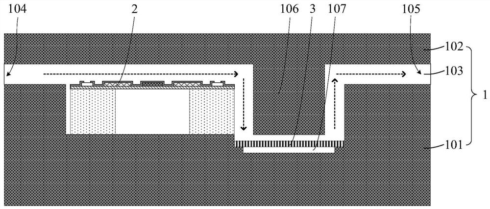
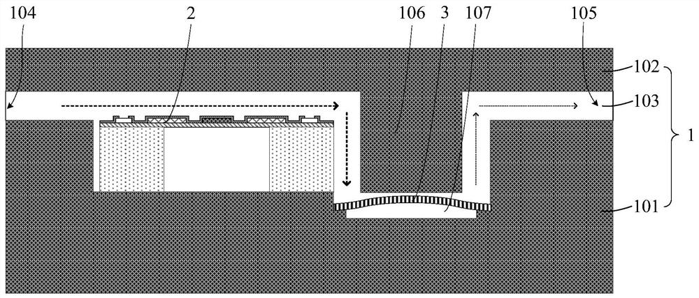
[0036] see figure 1 and figure 2 , a MEMS mass flow controller based on a piezoelectric control valve includes a housing 1, a mass flow sensor 2 and a piezoelectric diaphragm 3; channel 103; the mass flow sensor 2 is arranged on the relative left side of the lower substrate 101, that is, on the side near the inlet 104 of the airflow passage 103; side, the position of the piezoelectric diaphragm 3 is lower than the position of the mass flow sensor 2, and a downward protrusion 106 is provided on the inner side of the upper cover plate 102 corresponding to the position of the piezoelectric diaphragm 3, and the protrusion 106 is used to define the air flow channel The orientation of 103 makes the airflow channel 103 into a zigzag shape, so the airflow can be buffered to a certain extent. Both ends of the piezoelectric membrane 3 are disposed on the lower substrate 101 , and a vibration gap 107 is provided between the middle of the piezoelectric membrane 3 and the lower substrat...

Embodiment 2

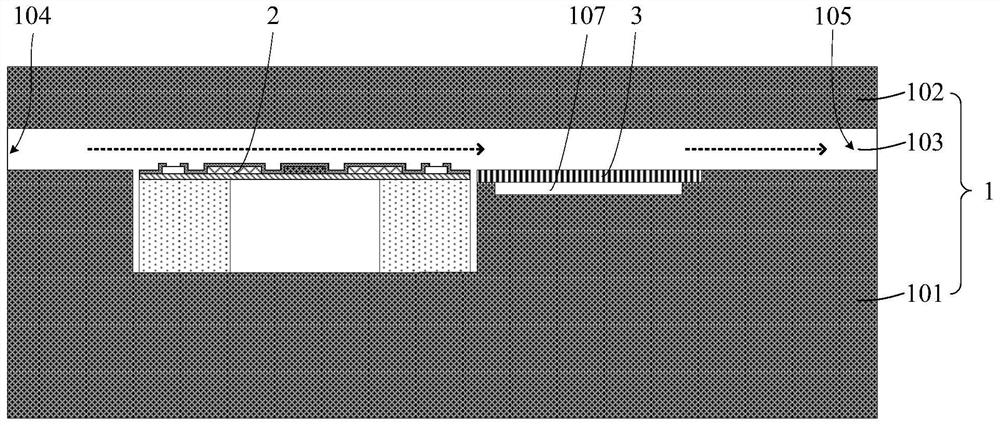
[0038] see image 3 and Figure 4 , a MEMS mass flow controller based on a piezoelectric control valve includes a housing 1, a mass flow sensor 2 and a piezoelectric diaphragm 3; channel 103; the mass flow sensor 2 is arranged on the relative left side of the lower substrate 101, that is, on the side near the inlet 104 of the airflow passage 103; On the side, both ends of the piezoelectric membrane 3 are arranged on the lower substrate 101 , and a vibration gap 107 is provided between the middle of the piezoelectric membrane 3 and the lower substrate 101 . The upper surfaces of the mass flow sensor 2 and the piezoelectric membrane 3 are located at the same level, and the airflow channel 103 is in the shape of a horizontal line.

[0039] Specifically, the casing 1 is made of airtight hard material, the lower base plate 101 and the upper base plate 102 are connected and fixed by methods such as welding, crimping, fastening, buckling, etc., and the cross-sectional shape of the ...


PUM


Abstract

The invention discloses an MEMS mass flow controller based on a piezoelectric control valve and a control method. The MEMS mass flow controller comprises a shell, a mass flow sensor and a piezoelectric diaphragm, wherein the mass flow sensor and the piezoelectric diaphragm are located in the shell, the shell comprises a lower base plate, an upper cover plate and an airflow channel defined by the lower base plate and the upper cover plate, the mass flow sensor is arranged on the side, close to an inlet of the airflow channel, of the lower base plate, the piezoelectric diaphragm is arranged on one side, close to the outlet of the airflow channel, of the lower substrate, the two ends of the piezoelectric diaphragm are arranged on the lower substrate, and a vibration gap is formed between the middle of the piezoelectric diaphragm and the lower substrate. According to the invention, the mass flow sensor is used for accurately measuring gas flow and feeding back the gas flow in real time, the gas flow serves as an adjusting basis of driving voltage of the piezoelectric diaphragm, and then high-precision control over micro flow can be achieved through deformation of the piezoelectric diaphragm; and the MEMS mass flow controller has the advantages of being simple in structure, small in size, low in cost, high in preparation controllability and the like.

Description

technical field [0001] The invention relates to the technical field of flow measurement and control, in particular to a piezoelectric control valve-based MEMS mass flow controller and a control method. Background technique [0002] Flow measurement and control are the basic needs of industrial production and scientific research. As a device that can directly measure and control the mass flow of gas, the mass flow controller plays an important role in many fields such as semiconductors and integrated circuits, petrochemicals, vacuum coating, medicine, and environmental protection. The core components of mass flow controllers include mass flow sensors and electromagnetic regulating valves. Among them, the sensor can realize the accurate measurement of the gas mass flow, and the electromagnetic regulating valve can adjust and control the flow according to the measurement result. [0003] At present, in domestic mass flow controllers, the sensor usually uses the principle of c...

Claims


Application Information

Patent Timeline
Patent Type & Authority Applications(China)
IPC IPC(8): G05D7/06B81B7/02
CPCG05D7/0635B81B7/02B81B2201/02
Inventor 胡国庆田伟
Owner 青岛芯笙微纳电子科技有限公司
Why Eureka
Try Eureka