Natural gas hydrate reservoir reinforcing method

A hydrate and natural gas technology, which is applied in earthwork drilling, wellbore/well components, sealing/isolation, etc., can solve problems such as limited reinforcement range, hydrate decomposition, low permeability of muddy silt reservoirs, etc. Achieve the effects of improving particle size distribution and soil composition ratio, promoting the improvement of seepage capacity, and expanding the scope of reinforcement

Pending Publication Date: 2021-08-03
SOUTH UNIVERSITY OF SCIENCE AND TECHNOLOGY OF CHINA
View PDF6 Cites 1 Cited by
  • Summary
  • Abstract
  • Description
  • Claims
  • Application Information

AI Technical Summary

Problems solved by technology

[0003] The existing reinforcement of natural gas hydrate reservoirs is mainly to inject cement slurry through the wellbore or artificially drilled small holes, and use the strength increase of cement to strengthen the hydrate reservoir. However, due to the high density of cement slurry and the mud Silt reservoirs have low permeability, and usually only cement stones with high strength will be formed in a small area near the wellbore and slimhole to strengthen the reservoir. The post-high-strength cement stone supports the formation near the wellbore
This method, on the one hand, can only reinforce the natural gas hydrate reservoir near the well, resulting in a limited reinforcement range and uneven reinforcement effect of the gas hydrate reservoir extending from the wellbore wall to the reservoir; on the other hand, the use of cement The way of pouring reinforcement will reduce the permeability of hydrate reservoirs and affect the production capacity of hydrates. At the same time, the heat generated by cement solidification will cause hydrates to decompose, which may affect the stability of hydrate reservoirs reinforcement.

Method used


Image

  • Natural gas hydrate reservoir reinforcing method
  • Natural gas hydrate reservoir reinforcing method
  • Natural gas hydrate reservoir reinforcing method

Examples


Embodiment Construction

[0036] It should be understood that the specific embodiments described here are only used to explain the present invention, not to limit the present invention.

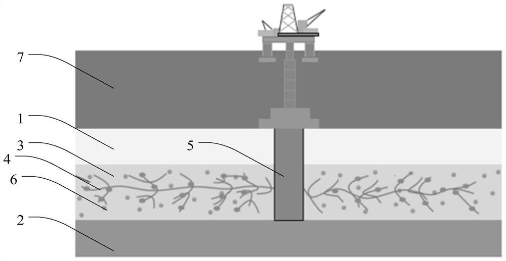
[0037] refer to figure 1 , the natural gas hydrate reservoir comprises an upper overburden 1 and a lower overburden 2, and between the upper overburden 1 and the lower overburden 2 is a hydrate zone 3 where gas hydrates are stored, and the hydrate zone 3 There are seepage channels 4. In this embodiment, the upper covering layer 1 is located at a sea depth of 1200m, the thickness of the upper covering layer 1 is 400m, the thickness of the hydrate zone 3 is 270m, and the seabed temperature is about 10°C , the seabed pressure is about 10 MPa, and there are seepage channels 4 in the hydrate zone 3, but it is not limited to this embodiment.

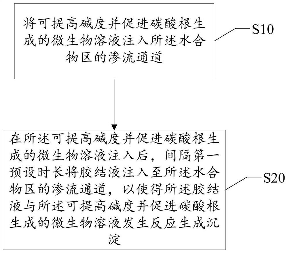
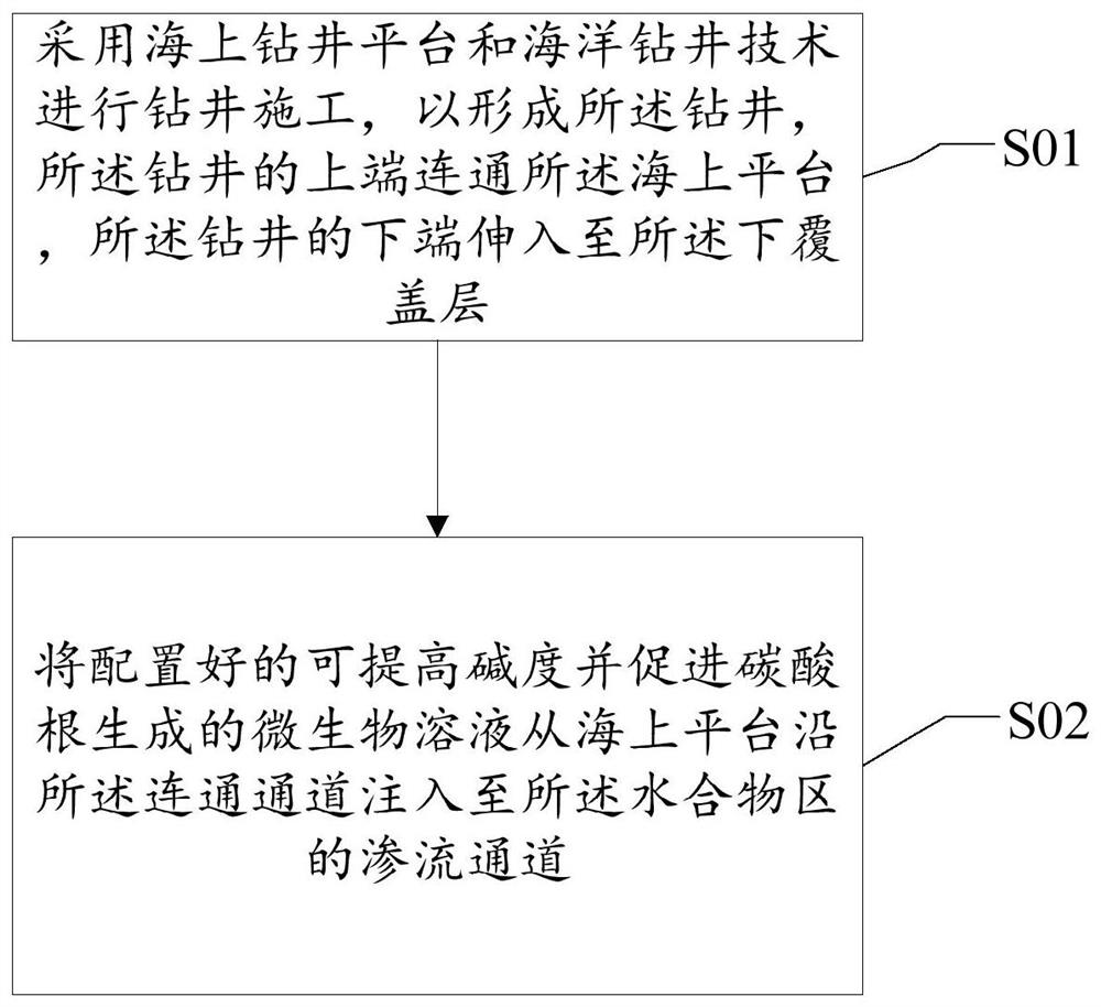
[0038] The embodiment of the present invention provides a natural gas hydrate reservoir strengthening method, referring to figure 2 , figure 2 It is a schematic flowchart of the ...


PUM


Abstract

The invention discloses a natural gas hydrate reservoir reinforcing method. A natural gas hydrate reservoir comprises an upper covering layer and a lower covering layer, wherein a hydrate area where a natural gas hydrate exists is arranged between the upper covering layer and the lower covering layer, and a seepage channel exists in the hydrate area. The natural gas hydrate reservoir reinforcing method comprises the steps of injecting a microbial solution capable of improving alkalinity and promoting generation of carbonate into the seepage channel of the hydrate area; and injecting a cementing fluid into the seepage channel of the hydrate area at a first preset time interval after injecting the microbial solution capable of improving the alkalinity and promoting the carbonate generation so as to enable the cementing fluid to react with the microbial solution capable of improving the alkalinity and promoting the carbonate generation to generate a precipitate. According to the natural gas hydrate reservoir reinforcing method, the reinforcing range of an argillaceous silt hydrate reservoir can be enlarged, the permeability of the argillaceous silt hydrate reservoir is improved while the argillaceous silt hydrate reservoir is reinforced, and the non-uniformity of the reinforcing effect of the hydrate reservoir along with the change of the horizontal distance, the particle size distribution of the hydrate and the proportion of soil components are improved.

Description

technical field [0001] The invention relates to the technical field of marine resources and basic engineering, in particular to a reinforcement method for natural gas hydrate reservoirs. Background technique [0002] Natural gas hydrate is a cage compound formed by methane and other hydrocarbon gases and water under high pressure and low temperature conditions. As a new type of clean combustion energy, it has the characteristics of high combustion density, wide distribution range and high content, and has become one of the hot spots in the field of energy science research. Existing exploration results show that natural gas hydrates are mainly distributed in the arctic permafrost and the deep water areas of 300-3000 m deep in the coastal continental shelf. Preliminary estimates indicate that the global natural gas hydrate resources are about 21×10 15 m 3 , and its resources are twice that of global carbon-containing compounds, about 95% of which occur in deep-sea areas. Th...

Claims


Application Information

Patent Timeline
Patent Type & Authority Applications(China)
IPC IPC(8): E21B33/13
CPCE21B33/13
Inventor 王誉泽杨建宇
Owner SOUTH UNIVERSITY OF SCIENCE AND TECHNOLOGY OF CHINA
Why Eureka
Try Eureka