

Staged pollution treatment device for thermal power plant
Patent Information
- Authority / Receiving Office
- CN · China
- Patent Type
- Applications(China)
- Current Assignee / Owner
- 陈怡
- Publication Date
- 2021-08-10
Smart Images
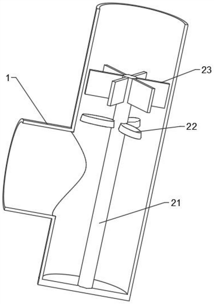
Figure 1 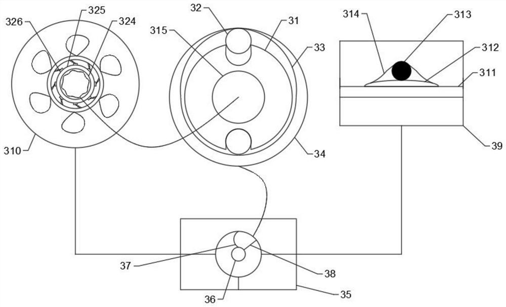
Figure 2 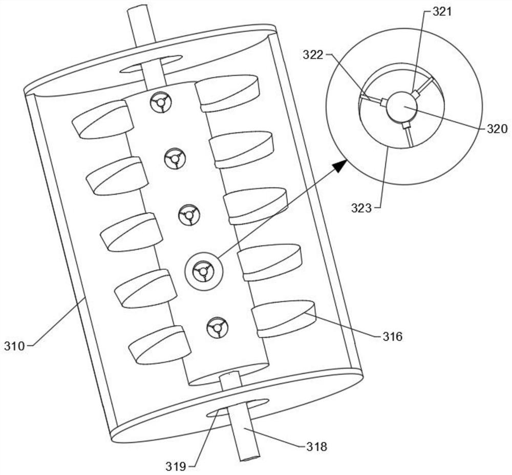
Figure 3
Abstract
Description
technical field
[0001] The invention relates to the technical field of pollution treatment, in particular to a graded pollution treatment device for thermal power plants. Background technique
[0002] During the whole process of producing electric energy in thermal power plants, the impact of various emissions on the environment exceeds a certain limit and causes the deterioration of environmental quality. These emissions include dust particles, ash, and smoke emitted from the fuel combustion process.
[0003] In the process of processing dust particles, ash, and flue gas, the content of dust particles, ash, and flue gas in the flue gas is called the ash content rate. If the ash content rate is too large, the filter device may be blocked. After the filter device is blocked, it will cause excessive dust particles, ash, and flue gas inside the stove, which will affect the oxygen content, and then affect the combustion efficiency of the remaining coal. When the ash content is l...