A piled offshore embankment and its design method and application

A single pile and form technology, applied in design optimization/simulation, special data processing applications, geometric CAD, etc., can solve the problems of unsatisfactory wave elimination effect of permeable breakwaters, restricting the application of permeable breakwaters, etc., and achieves construction difficulty. Low, good modulation effect, simple structure design effect

Active Publication Date: 2021-10-01
OCEAN UNIV OF CHINA
View PDF8 Cites 0 Cited by
  • Summary
  • Abstract
  • Description
  • Claims
  • Application Information

AI Technical Summary

Problems solved by technology

Under long-period wave conditions, the wave absorption effect of permeable breakwaters is not ideal, which limits the application of permeable breakwaters in practical engineering

Method used


Image

  • A piled offshore embankment and its design method and application
  • A piled offshore embankment and its design method and application
  • A piled offshore embankment and its design method and application

Examples


Embodiment 1

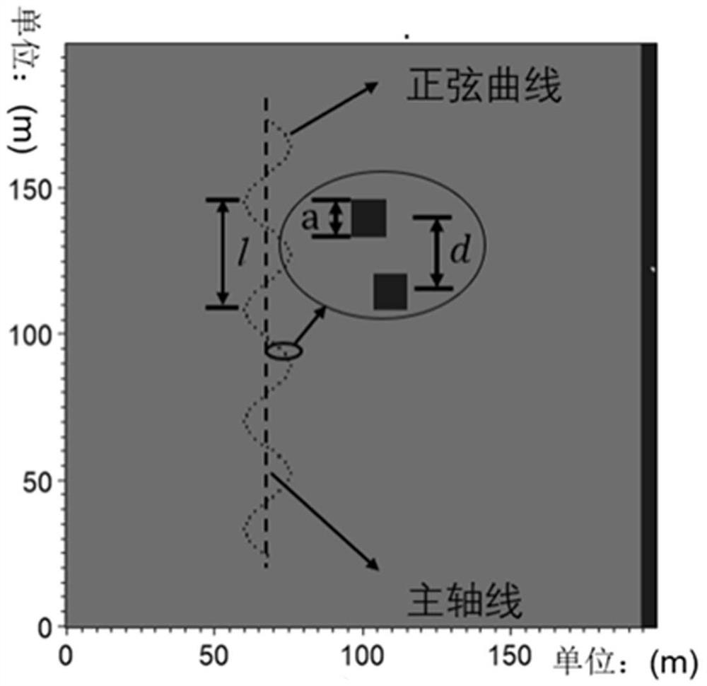
[0036] The utility model relates to a piled offshore embankment, and the arrangement structure of the piled offshore dike is in the form of a sinusoidal curve.

[0037] The sinusoidal wavelength of the control element of the piled offshore embankment (m) satisfy the grating theory, that is:

[0038]

[0039] in In order to shield the wave direction of medium-long and / or long-period waves within the scope of the sea area, is the corresponding wavelength, and the sinusoidal amplitude A is a non-control element, satisfying .

[0040] The spacing of the control element piles of the single piles of the piled offshore embankment With the number of single piles N, its main function is to block the incoming main wave of the sea area to be covered, which satisfies the multi-slit diffraction grating equation:

[0041]

[0042] in In order to cover the main wave direction of the sea area, is the dominant wavelength of the sea area to be protected, and N is the number ...

Embodiment 2

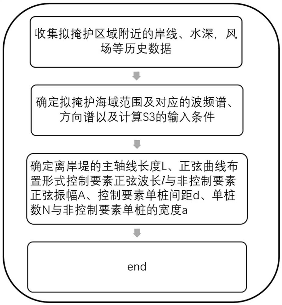
[0047] A method for designing piled offshore embankments, comprising the following steps:

[0048]S1. Collect the shoreline and water depth data near the area to be protected, as well as historical statistics such as the wind field of nearby hydrometric stations.

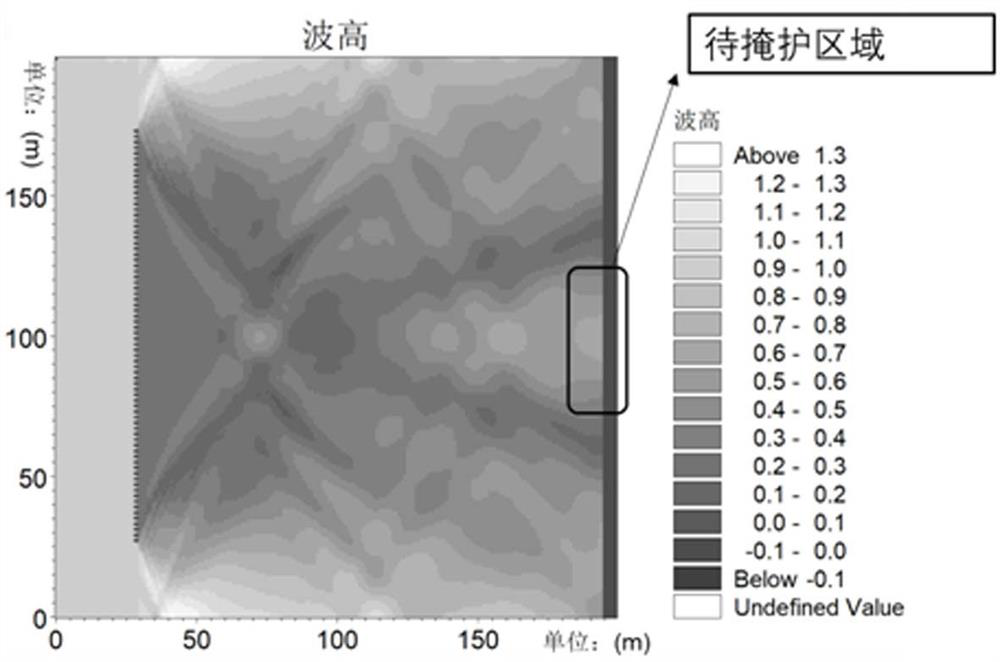
[0049] S2. Determine the scope of the sea area to be covered and the corresponding wave spectrum S ( ), the direction spectrum S ( , ) and determine the input condition of S3 from the wave spectrum and direction spectrum, the input condition is the main wave direction with dominant wavelength ; specifically include:

[0050] S21. Determine the concentrated frequency band range and spectral peak frequency of wave energy in the wave spectrum in the sea area to be shielded f 0 ,

[0051] S22. Determine the concentration distribution interval and main wave direction of the wave energy direction in the direction spectrum of the sea area to be covered ,

[0052] S23. Substitute the water depth and period da...


PUM


Abstract

The invention discloses a pile-type offshore embankment, a design method and an application thereof, and belongs to the technical field of coastal engineering. The layout structure of the piled offshore embankment is in the form of a sinusoidal curve. The design method includes: collecting historical data such as the coastline, water depth, and wind field near the area to be protected; determining the range of the sea area to be protected and the corresponding wave spectrum, direction spectrum and calculating Input conditions of S3; determine the main axis length L of the offshore embankment, the sinusoidal wave length (m) of the sinusoidal curve layout control elements and the sinusoidal amplitude A of the non-control elements, the single pile distance d of the control elements, the number of single piles N and the single pile of the non-control elements The width of the pile a. The sinusoidal array arrangement can effectively block the interference of long-period waves and avoid wave resonance in the area to be sheltered. At the same time, the single piles arranged in the array can effectively block the interference of short waves and expand the wave dissipation frequency from a narrow bandwidth to a wide frequency band, thereby Improve the wave-blocking efficiency of piled offshore dikes.

Description

technical field [0001] The invention relates to the technical field of coastal engineering, and more specifically relates to a design method for piled offshore dikes. Background technique [0002] Offshore breakwaters (referred to as offshore dikes) are currently more effective and widely used coastal protection structures. Offshore dikes are generally built parallel to the shoreline in the offshore waters off the beach, and are mainly suitable for coasts dominated by wave erosion. Different from purely fixed shorelines (seawalls and revetments) or purely intercepted sediments (groves), offshore dikes block the waves in the open sea and reduce the wave energy near the shore, so that the sediment will fall behind the dikes, thereby promoting beach surface broaden. Some studies have shown that the offshore embankment can not only block the lateral movement of sediment, but the spit (or island dam) formed thereafter also has a certain ability to intercept sand transport along...

Claims


Application Information

Patent Timeline
Patent Type & Authority Patents(China)
IPC IPC(8): G06F30/13G06F30/20
CPCG06F30/13G06F30/20
Inventor 梁丙臣葛洪丽张黎邦李华军夏天汪邵伟王晓霞
Owner OCEAN UNIV OF CHINA
Why Eureka
Try Eureka