A two-stage swirl urea injector

A technology of injector and urea, applied in the direction of machine/engine, mechanical equipment, engine components, etc., can solve the problems of difficult to meet the atomization effect, flow consistency, poor processing technology, and difficult to ensure the consistency of atomized particle size.

Active Publication Date: 2022-02-11
NANYUE FUEL INJECTION SYST CO LTD
View PDF6 Cites 0 Cited by
  • Summary
  • Abstract
  • Description
  • Claims
  • Application Information

AI Technical Summary

Problems solved by technology

With the improvement of discharge requirements, the particle size requirements of spray particles are getting higher and higher. The atomization effect of this structure is difficult to meet the current requirements. It is difficult to ensure the consistency of atomized particle size between holes, and the flow consistency and processing technology are poor

Method used


Image

  • A two-stage swirl urea injector
  • A two-stage swirl urea injector
  • A two-stage swirl urea injector

Examples


Embodiment Construction

[0028] Structure of the present invention, further concrete description is as follows in conjunction with accompanying drawing:

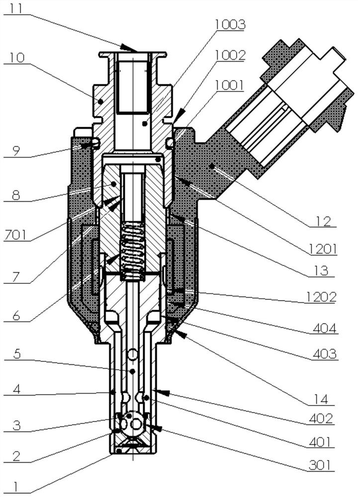
[0029] see Figure 1 to Figure 6 , the two-stage swirl urea injector shown in the figure mainly includes the electromagnet part 12, the oil inlet joint, the iron core spring assembly and the injection valve assembly. The oil inlet joint includes a filter screen support 10, a filter screen 11 and an O-ring seal 9. A middle hole 1003 is arranged in the filter screen support 10 , and the filter screen 11 is placed in the middle hole 1003 .

[0030] The iron core spring assembly includes an iron core 8 , a spring upper seat 7 and a spring 6 .

[0031] The injection valve assembly includes a valve stem 5 , a nozzle body 4 , a steel ball 3 , a valve seat 2 , and a nozzle plate 1 .

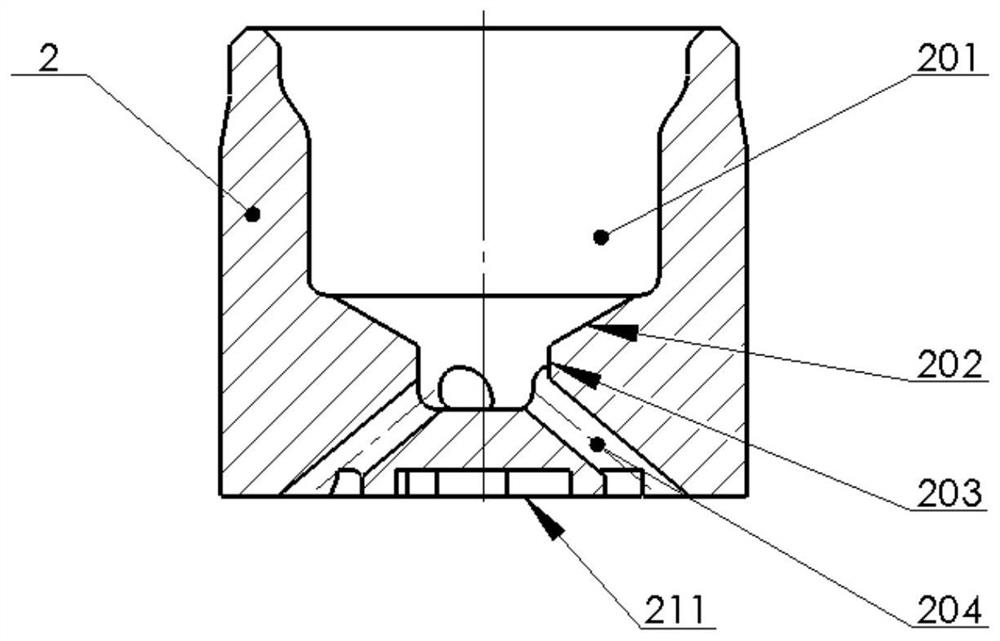
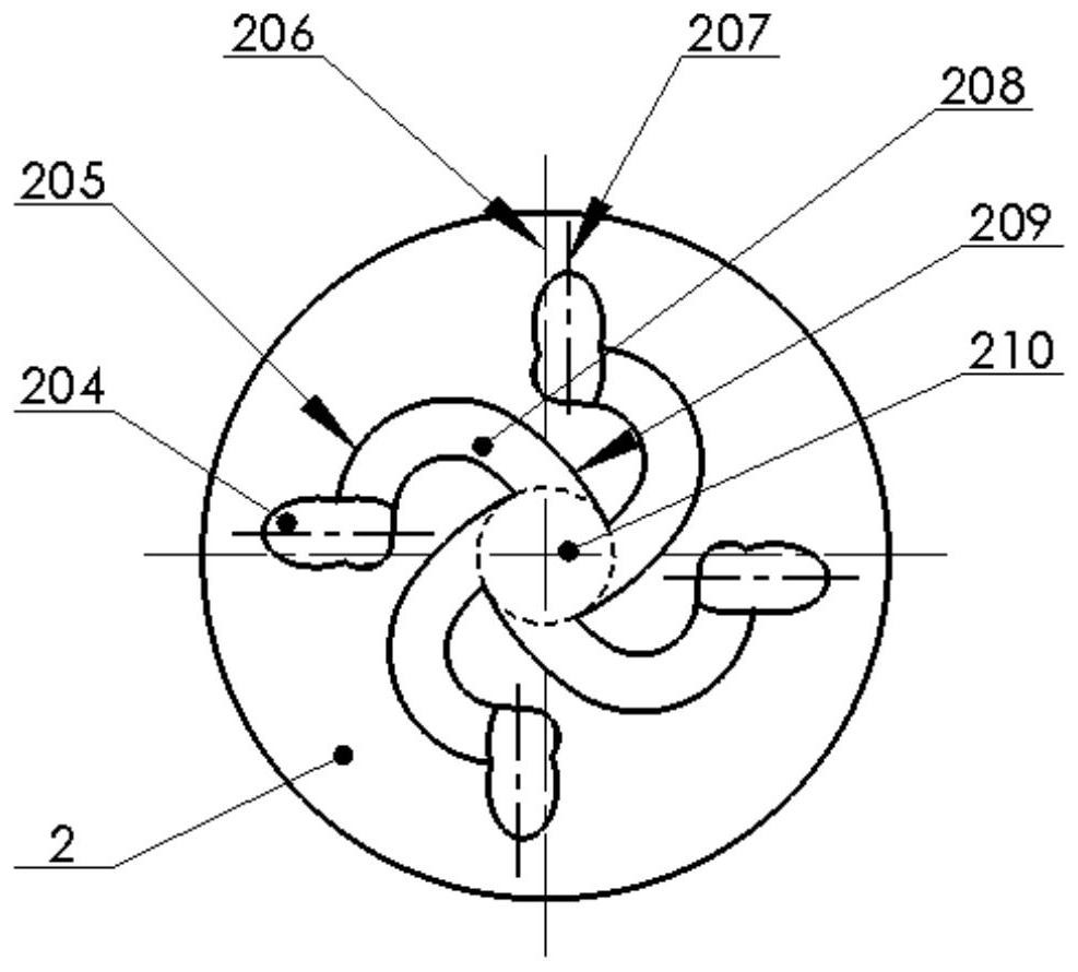
[0032] The valve seat 2 is fixed at the lower end of the inner hole 402 of the nozzle body 4 by laser welding. See especially figure 2 and image 3 , The valve seat 2 i...


PUM


Abstract

The invention discloses a two-stage swirl urea injector, which at least includes a nozzle body, a valve stem, a valve seat, a nozzle plate, and a steel ball. The center of the valve seat is eccentrically arranged relative to the central axis of the valve seat; several swirl grooves and a swirl hole are arranged on the lower surface of the valve seat, and the swirl hole is located at the center of the lower surface of the valve seat And coaxially penetrate the round hole of the nozzle plate; the first end of each inclined hole communicates with the flow hole, the first end of each swirl groove communicates with the second end of the corresponding inclined hole, each The second end of a swirl groove communicates with the swirl hole. The invention has the advantages of being able to improve the particle size of atomized particles, improving flow consistency, simple and reasonable structure, convenient manufacture and assembly, and low production cost.

Description

technical field [0001] The invention belongs to the technical field of automobile manufacturing, in particular to a two-stage swirl urea injector. Background technique [0002] Selective Catalytic Reduction (Selective Catalytic Reduction) referred to as SCR, SCR is installed in the exhaust system of diesel vehicles to catalytically reduce NOx in diesel engine emissions to N 2 and H 2 O catalytic reduction device, select urea aqueous solution as the reducing agent. In the SCR system, the urea injector sprays the urea aqueous solution into the exhaust pipe regularly and quantitatively. The better the atomization effect of the urea aqueous solution, the more sufficient the exhaust reaction can be, and it is not easy to crystallize. In actual use, due to poor atomization effect in the post-treatment system, urea crystallization blockage frequently occurs, resulting in excessive emissions or insufficient vehicle power. [0003] The Chinese utility model patent application numb...

Claims


Application Information

Patent Timeline
Patent Type & Authority Patents(China)
IPC IPC(8): F01N3/20F01N3/28
CPCF01N3/2066F01N3/28F01N2610/02F01N2610/1453Y02T10/12Y02A50/20
Inventor 邓飞李成校欧阳玲湘陈勤学任学成吴峰胜龙美彪黄民备伍新义
Owner NANYUE FUEL INJECTION SYST CO LTD
Why Eureka
Try Eureka