Supercharge Your Innovation With Domain-Expert AI Agents!

Beam forming method and system based on output enhancement of horizontal line array

A horizontal line and beam technology, applied in the field of beamforming methods and systems for enhanced output, can solve the problems of inability to use passive sonar signal processing, relying on sound source distance information, etc., and achieve excellent output signal fidelity and high processing gain. , the effect of simple operation

Active Publication Date: 2021-08-20
INST OF ACOUSTICS CHINESE ACAD OF SCI
View PDF29 Cites 4 Cited by
  • Summary
  • Abstract
  • Description
  • Claims
  • Application Information

AI Technical Summary

Problems solved by technology

However, this method relies heavily on sound source distance information and cannot be used in passive sonar signal processing

Method used


Image

  • Beam forming method and system based on output enhancement of horizontal line array
  • Beam forming method and system based on output enhancement of horizontal line array
  • Beam forming method and system based on output enhancement of horizontal line array

Examples


Embodiment 1

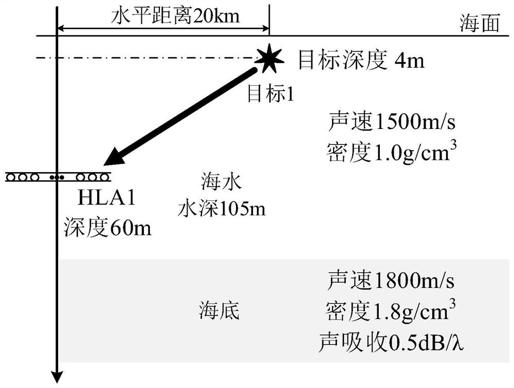
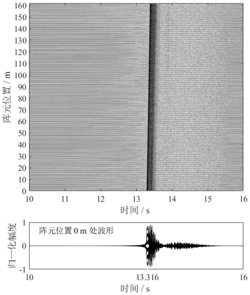
[0087] This embodiment is a beamforming method using passive sonar output enhancement, and its simulation experiment parameters are as follows figure 2 As shown, a shallow sea waveguide with a water depth of 105m and a water density of 1g / cm 3 , the sound velocity of the water body is 1500m / s, the water body has no absorption of sound waves, the seabed is set as an infinite half-space, and the density of the seabed medium is 1.8g / cm 3 , the sound velocity of the seabed medium is 1800m / s, and the sound absorption of the seabed medium is 0.5dB / λ, where λ represents the wavelength of the sound wave. A horizontal line array (HLA1) with 161 elements at an element interval of 1m is placed at a water depth of 60m, the horizontal distance between the stationary target 1 with an azimuth of -60° and the center of the array is 20km, and the depth of target 1 is 4m . The frequency range of the simulated pulse signal transmitted by target 1 is 680-720 Hz, and its spectrum Ω(ω) satisfies...

Embodiment 2

[0108] This embodiment is a beamforming method using active sonar output enhancement, and the simulation experiment parameters are as follows Image 6 As shown, a shallow sea waveguide with a water depth of 100m and a water density of 1g / cm 3 , the sound velocity of the water body is 1500m / s, the water body has no absorption of sound waves, the seabed is set as an infinite half-space, and the density of the seabed medium is 2.0g / cm 3 , the sound velocity of the seabed medium is 1600m / s, and the sound absorption of the seabed medium is 0.25dB / λ. A horizontal array (HLA2) with 1m array elements and 81 array elements is placed at a water depth of 60m. HLA2 has the function of transmitting and receiving active detection signals at the same time. The horizontal distance between the acoustic transponder and the center of the array is 5km, and the depth of target 2 is 4m. HLA2 emits a linear frequency modulation (LFM) signal with a frequency range of 330-430Hz and a pulse time widt...


PUM


Abstract

The invention belongs to the technical field of underwater acoustic detection and sonar, and particularly relates to an output-enhanced beam forming method and system based on a horizontal line array. The method comprises steps of enabling each array element in the horizontal line array to record the time domain waveform of a pulse signal received by the array element at the same time point for a certain shallow sea area; performing Fourier transform on the pulse time domain waveform recorded by each array element to obtain frequency domain sound pressure data of each array element signal, and performing spectral analysis on the frequency domain sound pressure data of each array element signal to obtain sound intensity data of each array element signal; drawing an image in which the sound intensity is jointly distributed along with the frequency-array element position according to the sound intensity data of each array element signal, and detecting interference fringes in the distributed image; performing phase compensation on the frequency domain sound pressure data of each array element signal to obtain compensated frequency domain sound pressure data of each array element signal, and obtaining frequency domain sound pressure data required for beam forming; and calculating beam output pointing to the target azimuth according to a weight coefficient required by beam forming.

Description

technical field [0001] The invention belongs to the technical fields of underwater acoustic array signal processing, underwater acoustic target azimuth estimation, underwater acoustic detection and sonar, and in particular relates to a beamforming method and system based on output enhancement of a horizontal line array. Background technique [0002] Target orientation estimation using conventional beamforming is widely used in underwater acoustic signal processing. Conventional beamforming theory is based on the propagation law of plane wave signals in free space, but there are two natural boundaries between the sea surface and the seabed in the actual shallow sea waveguide, and the actual sound wave transmission is more described by cylindrical wave theory, which is expressed as a synthesis of normal waves of different modes effect. The normal waves of each mode interfere with each other during transmission, forming light and dark interference fringes in the sound intensit...

Claims


Application Information

Patent Timeline
Patent Type & Authority Applications(China)
IPC IPC(8): G01S7/524G01S7/526
CPCG01S7/524G01S7/526
Inventor 刘昌鹏周士弘戚聿波顾怡鸣
Owner INST OF ACOUSTICS CHINESE ACAD OF SCI
Features
  • R&D
  • Intellectual Property
  • Life Sciences
  • Materials
  • Tech Scout
  • Unparalleled Data Quality
  • Higher Quality Content
  • 60% Fewer Hallucinations
Learn More