Coupling system of flameless combustion and coal pyrolysis oil extraction system

A flameless combustion and coupling system technology, applied in the field of coupling systems, can solve the problems of restricting the promotion and application of flameless combustion, resource waste, environmental pollution, etc., and achieve the effect of reducing heat transfer efficiency and simplifying configuration

Active Publication Date: 2021-08-24
XIAN THERMAL POWER RES INST CO LTD
View PDF4 Cites 0 Cited by
  • Summary
  • Abstract
  • Description
  • Claims
  • Application Information

AI Technical Summary

Problems solved by technology

However, at present, high-temperature semi-coke other than high-value-added tar products cannot be efficiently utilized, and it needs to be cooled, resulting in a certain degree of waste of resources and environmental pollution
[0003] Flameless combustion is a high-temperature and low-oxygen diffuse combustion method, which has the characteristics of high combustion efficiency, stable combustion, and very little pollutant generation. It is known as one of the most promising combustion technologies in the 21st century, and has been used in steel Industrial applications have been realized on gas furnaces such as metallurgy and metallurgy, and good energy-saving and environmental protection effects have been achieved. At present, the flameless combustion of gas fuels mostly uses high jets to improve the mixing degree of fuel and oxidant, and cooperates with high-temperature air to achieve a temperature higher than that of the entire combustion space. However, due to the low temperature of the heating medium in coal-fired boilers, it is difficult for fuel and oxidant to further increase the temperature, which limits the promotion and application of flameless combustion in the coal-fired field

Method used


Image

  • Coupling system of flameless combustion and coal pyrolysis oil extraction system

Examples


Embodiment Construction

[0023] Exemplary embodiments of the present disclosure will be described in more detail below with reference to the accompanying drawings. Although exemplary embodiments of the present disclosure are shown in the drawings, it should be understood that the present disclosure may be embodied in various forms and should not be limited by the embodiments set forth herein. Rather, these embodiments are provided for more thorough understanding of the present disclosure and to fully convey the scope of the present disclosure to those skilled in the art. It should be noted that, in the case of no conflict, the embodiments of the present invention and the features in the embodiments can be combined with each other. The present invention will be described in detail below with reference to the accompanying drawings and examples.

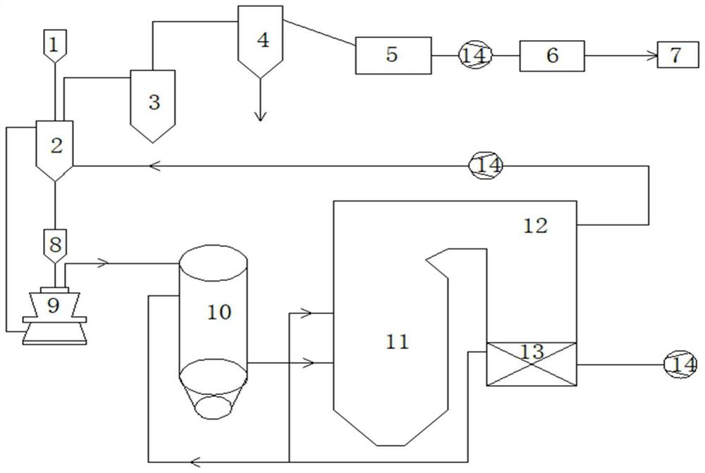
[0024] Such as figure 1 As shown, a coupling system of flameless combustion and coal pyrolysis oil extraction system provided by the present invention includ...


PUM


Abstract

The invention discloses a coupling system of a flameless combustion and coal pyrolysis oil extraction system. The coupling system comprises a pulverized coal pyrolysis device and the like. A heating heat source of the pulverized coal pyrolysis device is taken from high-temperature low-oxygen flue gas generated by coke breeze combustion at a steering chamber, pyrolysis pulverized coal is subjected to a pyrolysis reaction in the pulverized coal pyrolysis device, a pyrolysis reaction product is separated out and enters a gas-liquid separator through a cyclone dust collector to separate water and tar; light gasoline is separated out through an intercooler, after pressurization, tar removal and desulfurization are conducted through an air blower, pyrolysis coal gas is generated, and one part of the pyrolysis coal gas enters acoal gas holder through a desulfurization box; high-temperature coke breeze generated by a pulverized coal pyrolysis device enters a coal mill through a coke bin, and high-temperature flue gas at an outlet of the pulverized coal pyrolysis device is fed into a flameless combustion device; and meanwhile, high-temperature air at an outlet of an air preheater arranged in a flue gas pipeline is fed into the flameless combustion device and a secondary combustion chamber of a boiler in a grading manner, and staged combustion is realized. The coal grading, efficient and clean utilization can be realized.

Description

technical field [0001] The invention relates to a coupling system of flameless combustion and coal pyrolysis oil extraction system. Background technique [0002] The status quo of my country's energy structure rich in coal and low in oil determines the important position of coal in my country's energy strategy. At present, bituminous coal and lignite are mostly used for direct combustion, but direct combustion wastes the potential high value-added oil and gas in young coal. If the coal pyrolysis technology is adopted, the liquid and gas fuels urgently needed in our country can be obtained, and the comprehensive utilization rate of young coal types can be improved. Coal pyrolysis technology refers to the process of thermally decomposing coal in a non-oxidizing atmosphere to produce tar, gas and semi-coke. However, at present, high-temperature semi-coke other than high-value-added tar products cannot be efficiently utilized, and it needs to be cooled, resulting in a certain ...

Claims


Application Information

Patent Timeline
IPC IPC(8): C10B53/04C10B57/00C10B57/18
CPCC10B53/04C10B57/00C10B57/18Y02P20/129
Inventor 周广钦姚伟张喜来方顺利王志超李宇航贾子秀杜智华
Owner XIAN THERMAL POWER RES INST CO LTD
Why Eureka
Try Eureka