Extreme ultraviolet radiation control method and device, electronic device and extreme ultraviolet radiation system

A technology of extreme ultraviolet radiation and a control method, which is applied in the fields of devices, electronic equipment, extreme ultraviolet radiation systems, and extreme ultraviolet radiation control methods, can solve the problems of difficult control, low conversion efficiency of plasma extreme ultraviolet radiation, and difficulty in increasing light source power. It can improve the degree of ionization, reduce the production cost and improve the conversion efficiency.

Active Publication Date: 2021-08-24
GUANGDONG INTELLIGENT ROBOTICS INST
View PDF6 Cites 0 Cited by
  • Summary
  • Abstract
  • Description
  • Claims
  • Application Information

AI Technical Summary

Problems solved by technology

[0005]However, the pumping laser of the existing laser plasma light source is the laser light generated by the carbon dioxide laser, which needs to be transmitted in the air and reflected into the lithography light source system, and Two lasers are required to generate different pre-pulses and main pulses to heat the droplet target respectively, which is difficult to control, and it is difficult to increase the power of the light source, resulting in low plasma extreme ultraviolet radiation conversion efficiency

Method used


Image

  • Extreme ultraviolet radiation control method and device, electronic device and extreme ultraviolet radiation system
  • Extreme ultraviolet radiation control method and device, electronic device and extreme ultraviolet radiation system
  • Extreme ultraviolet radiation control method and device, electronic device and extreme ultraviolet radiation system

Examples


Embodiment Construction

[0039] In order to make the purpose, technical solution and advantages of the present application clearer, the present application will be further described in detail below in conjunction with the accompanying drawings and embodiments. It should be understood that the specific embodiments described here are only used to explain the present application, and are not intended to limit the present application.

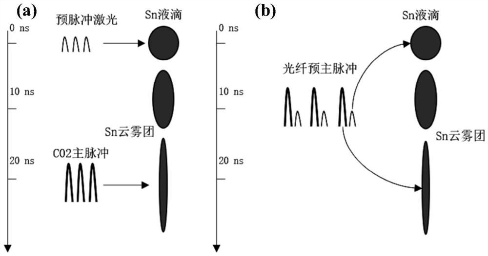
[0040] In one of the examples, as figure 1 As shown, (a) is a schematic diagram of the principle of a traditional extreme ultraviolet radiation device, in which the pre-pulse laser and the main pulse laser are two-way lasers, respectively emitted by two different pre-pulse lasers and main pulse lasers, (b) is Schematic diagram of the principle of the extreme ultraviolet radiation device of the embodiment of the present application, wherein the pre-pulse laser and the main pulse laser are emitted by the same laser, and there is a time delay between the pre-pulse laser and t...


PUM


Abstract

The invention relates to an extreme ultraviolet radiation control method and device, an electronic device and an extreme ultraviolet radiation system. The method comprises the following steps of outputting a liquid drop control instruction, wherein the liquid drop control instruction is used for controlling a liquid drop target generation device to generate liquid drops at a preset speed at a preset time interval; after the liquid drops reach a preset position, outputting a pre-pulse laser control instruction, wherein the pre-pulse laser control instruction is used for controlling a laser device to emit pre-pulse laser, so that the liquid drops generate cloud and mist clusters under the bombardment action of the pre-pulse laser; after the cloud and mist clusters reach the preset diffusion degree and the preset moving speed, outputting a main pulse laser control instruction, wherein the main pulse laser control instruction is used for controlling the same laser to emit main pulse laser, the cloud and mist clusters are made to generate plasma under the bombardment action of the main pulse laser, and the plasma is used for generating extreme ultraviolet radiation. By adopting the method provided by the embodiment of the invention, the plasma extreme ultraviolet radiation conversion efficiency can be effectively improved.

Description

technical field [0001] The present application relates to the field of laser technology, in particular to an extreme ultraviolet radiation control method, device, electronic equipment and extreme ultraviolet radiation system. Background technique [0002] Photolithography, as one of the core technologies in the semiconductor industry, is a patterning technology used in chip manufacturing. The light source used in lithography technology ranges from 436 nm to 356 nm, 248 nm, 193 nm... The line width required for lithography is getting smaller and smaller, and the wavelength of the light source is getting shorter and shorter. The wavelength range of light sources has evolved from the deep ultraviolet to the extreme ultraviolet range. [0003] At present, there are mainly four schemes to obtain extreme ultraviolet light sources, namely: synchrotron radiation source, laser plasma, discharge plasma and laser-assisted discharge plasma. Which solution to choose and how to use it t...

Claims


Application Information

Patent Timeline
IPC IPC(8): G03F7/20H04N5/247
CPCG03F7/70033H04N23/90
Inventor 马修泉王力波闻锦程吴寒刘怀亮马新敏陆培祥
Owner GUANGDONG INTELLIGENT ROBOTICS INST
Why Eureka
Try Eureka