
Camera calibration device and method for microscopic three-dimensional shape measurement system

A camera calibration and measurement system technology, which is applied in the field of three-dimensional microscopic shape measurement, can solve the problems of loss of measurement accuracy, inaccurate calibration target positioning, lens distortion perspective, etc., to achieve improved extraction accuracy, high robustness, and improved accuracy Effect

Active Publication Date: 2021-08-24
SICHUAN UNIV
View PDF12 Cites 2 Cited by
  • Summary
  • Abstract
  • Description
  • Claims
  • Application Information

AI Technical Summary

Problems solved by technology

[0004] The purpose of the present invention is to overcome the method of extracting feature points in the prior art that is easily affected by the quality of the picture, resulting in loss of measurement accuracy, inaccurate positioning of the calibration target, and lens distortion and perspective distortion lead to inaccurate feature points extracted, providing a camera calibration device and method for a microscopic three-dimensional shape measurement system

Method used


Image

  • Camera calibration device and method for microscopic three-dimensional shape measurement system
  • Camera calibration device and method for microscopic three-dimensional shape measurement system
  • Camera calibration device and method for microscopic three-dimensional shape measurement system

Examples


Embodiment 1

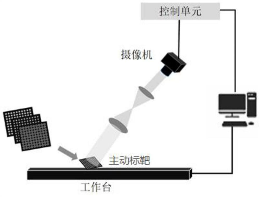
[0043] like figure 2 Shown, build workbench, video camera that telecentric lens is housed, control unit, calculation unit, also have digital display device, the used calculation unit of present embodiment is computer, and digital display device is LCD display screen; Digital display device is used for The active target generated by the simulation is displayed, and the calculation unit is a computer, which is used to execute the calibration method described in this embodiment.

[0044] In this field, after the active target is photographed, the photographed picture obtained is called a calibration picture.

[0045] A camera calibration method for a microscopic three-dimensional shape measurement system, comprising the following steps:

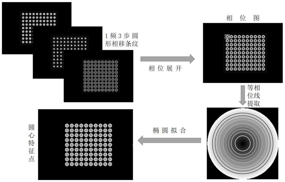
[0046]S0, using the simulation algorithm to generate an active target, the active target displays a center feature point, that is, a circular phase shift fringe, the specific method is as follows:

[0047] like image 3 As shown in the upper...

Embodiment 2

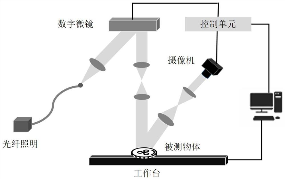
[0089] like figure 1 As shown, a microscopic measurement system based on orthographic projection and phase circle target is constructed, including: a three-dimensional microscopic measurement system, and a phase target displayed by LCD. Wherein, the three-dimensional microscopic measurement system includes a workbench, an optical fiber lighting source, a digital micromirror (DMD), a camera, and a computer, and the camera has been calibrated using the calibration device and method of Embodiment 1;


PUM


Abstract

The invention relates to the field of three-dimensional morphology measurement, and particularly discloses a camera calibration method and device for a 3D microscopic shape measurement system, and the method comprises the steps: generating a phase target, carrying out the snapshot of a camera, carrying out the phase analysis of a snapshot calibration picture, generating a phase diagram, extracting the feature point of the circle center of an integer pixel from the phase diagram, performing equiphase line extraction in a D * D neighborhood of a pixel size such as 35 * 35 by taking the whole image circle center feature point as a center, performing ellipse fitting to obtain a sub-pixel precision circle center feature point, and calculating a camera parameter initial value according to a telecentric camera calibration algorithm according to a pixel coordinate of the sub-pixel precision circle center feature point and a corresponding world coordinate; and obtaining high-precision camera parameters by using a repeated iteration method. The device and method have very high robustness to image blurring and noise, the target is more accurate, and the extraction of the circle center feature point is not influenced by lens distortion and perspective distortion.

Description

technical field [0001] The invention relates to the field of three-dimensional microscopic shape measurement, in particular to a camera calibration device and method for a microscopic three-dimensional shape measurement system. Background technique [0002] With the advent of Industry 4.0, micro devices with dimensions in millimeters and microns have been widely used and have huge market demands in the fields of defense industry, information technology, aerospace, microelectronics, and biomedicine. Precision manufacturing technology has also developed rapidly, and the precise three-dimensional inspection of the surface of complex parts and its tiny structural features has become a common demand in the industry. In particular, high-precision three-dimensional shape detection technology will be an important quality control tool for micro-device processing and manufacturing, as well as the basis and guarantee for high-precision device processing. The surface structure features...

Claims


Application Information

Patent Timeline
IPC IPC(8): G06T7/80G06T7/66G06T3/40
CPCG06T7/85G06T7/66G06T3/4007G06T2207/10056G06T2207/30208
Inventor 朱江平安世勇周佩肖雯帆
Owner SICHUAN UNIV
Learn More