
A magnetic ellipsometry measuring device

A measuring device and ellipsometric technology, which is applied in the direction of measuring device, magnetic performance measurement, polarization influence characteristics, etc., can solve the problem that it is impossible to obtain richer information on the magneto-optical characteristics of magnetic samples, the information obtained is limited, and the magneto-optical characteristics of materials cannot be realized. Measurement and other issues, to achieve the effect of rich functions, single influencing factors, and easy expansion

Active Publication Date: 2022-07-05
HUAZHONG UNIV OF SCI & TECH
View PDF9 Cites 0 Cited by
  • Summary
  • Abstract
  • Description
  • Claims
  • Application Information

AI Technical Summary

Problems solved by technology

The above devices are important instruments for the study of magnetic phenomena. However, these instruments can only measure some magneto-optical properties, such as magnetic moment, etc., and cannot obtain richer information related to the magneto-optical properties of magnetic samples.
However, when the magnetic field loading device is integrated on the basis of the ellipsometry method, the characterization of the magneto-optical Kerr effect and the magneto-optic Faraday effect can be realized, but these methods cannot realize the measurement of the magneto-optical properties of materials under any magnetic field orientation and any magnetic field strength. , and the information obtained is relatively limited

Method used


Image

  • A magnetic ellipsometry measuring device
  • A magnetic ellipsometry measuring device
  • A magnetic ellipsometry measuring device

Examples


Embodiment Construction

[0031] In order to make the objectives, technical solutions and advantages of the present invention clearer, the present invention will be further described in detail below with reference to the accompanying drawings and embodiments. It should be understood that the specific embodiments described herein are only used to explain the present invention, but not to limit the present invention. In addition, the technical features involved in the various embodiments of the present invention described below can be combined with each other as long as they do not conflict with each other.

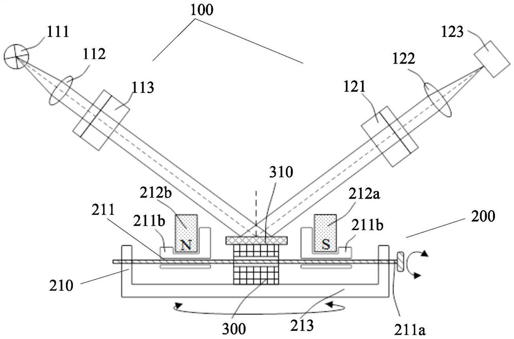
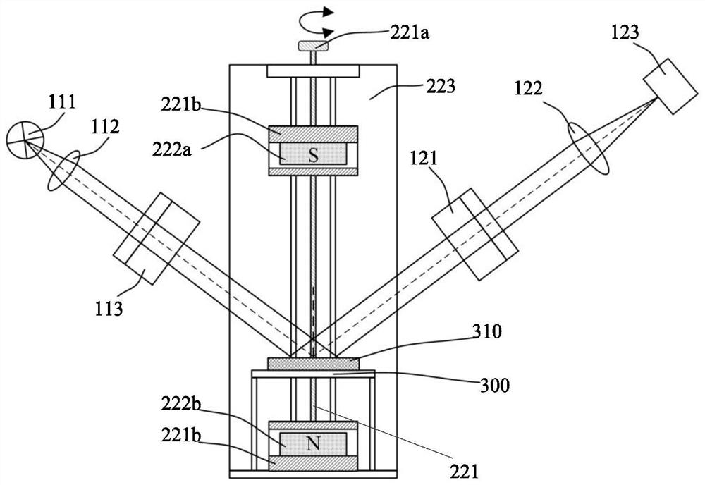
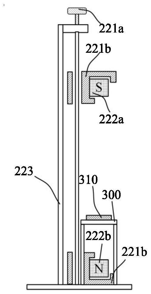
[0032] see figure 1 and figure 2 , the present invention provides a magneto-optical ellipsometry measurement device, the device includes an ellipsometry measurement module 100 , a magnetic field loading module 200 and a sample stage 300 . Among them, the magnetic field loading module 200 can apply transverse magnetic field loading, vertical magnetic field loading, arbitrary horizontal azimuth mag...


PUM

PropertyMeasurementUnit
wavelengthaaaaaaaaaa

Abstract

The invention belongs to the technical field of optical measurement, and discloses a magnetic ellipsometry measurement device. The device comprises an ellipsometry measurement module, a magnetic field loading module and a sample stage. The ellipsometric measurement module is used to perform optical measurement on a sample, and the magnetic field loading module includes A horizontal magnetic field loading module and a vertical magnetic field loading module, wherein the horizontal magnetic field loading module includes a horizontal moving component, a first permanent magnet pole pair, and a rotating table, the rotating table is used to drive the horizontal moving component to rotate in a horizontal plane, and the horizontal moving component is used for The two magnets in the first permanent magnet pole pair are moved towards each other or back; the vertical magnetic field loading module includes a vertical movement component and a second permanent magnet pole pair, and the vertical movement component makes the two magnets of the second permanent magnet pole pair face the sample The tables move toward or away from each other. In this application, ellipsometry parameters and Mueller matrix measurements can be performed on samples to be tested under different magnetic field strengths and different modes of magnetic fields.

Description

technical field [0001] The invention belongs to the technical field of optical measurement, and more particularly, relates to a magnetic ellipsometry measurement device. Background technique [0002] When there is an external magnetic field loaded, the magnetization intensity, magnetization direction, magnetization coupling coefficient and dielectric tensor of the magnetic material will change, so that the optical properties of the magnetic material will change. The physical phenomenon is often referred to as the magneto-optical effect. At present, magnetic devices such as magneto-optical storage, magneto-optical isolation, magneto-optical switches, magneto-optical modulation, spintronics, magnetic sensing, etc. have been developed using the magneto-optical effect characteristics of magnetic materials, and are widely used in semiconductors, energy, medical and defense technology and other fields. In-depth knowledge and a thorough understanding of the magneto-optical proper...

Claims


Application Information

Patent Timeline
Patent Type & Authority Patents(China)
IPC IPC(8): G01N21/21G01N21/01G01R33/12
CPCG01N21/211G01N21/01G01R33/12G01N2021/218
Inventor 刘世元刘佳敏江浩龚雯棋
Owner HUAZHONG UNIV OF SCI & TECH
Learn More