A kind of magnetic steel production equipment for motor

A technology for production equipment and magnets, which is applied in the field of magnets production equipment for motors, can solve the problems of temperature sensitivity of magnets, affecting the stability of magnetization and permeability of magnets, and reducing the quality of magnets, so as to reduce Effects of heating, reducing residual moisture, and increasing property stability

Active Publication Date: 2022-04-05
徐州给力磁业有限公司
View PDF6 Cites 0 Cited by
  • Summary
  • Abstract
  • Description
  • Claims
  • Application Information

AI Technical Summary

Problems solved by technology

[0006] In order to make up for the deficiencies of the prior art, when the magnetic steel sheet is cut by the cutting device in the prior art, since the magnetic steel sheet is sensitive to temperature, the overheating of the magnetic steel sheet during the cutting process will easily affect the magnetic permeability of the magnetic steel sheet. The stability of magnetic properties reduces the quality of magnetic steel sheets, and the present invention proposes a production equipment for magnetic steel for motors

Method used


Image

  • A kind of magnetic steel production equipment for motor
  • A kind of magnetic steel production equipment for motor
  • A kind of magnetic steel production equipment for motor

Examples


Embodiment 1

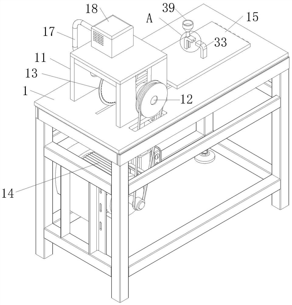
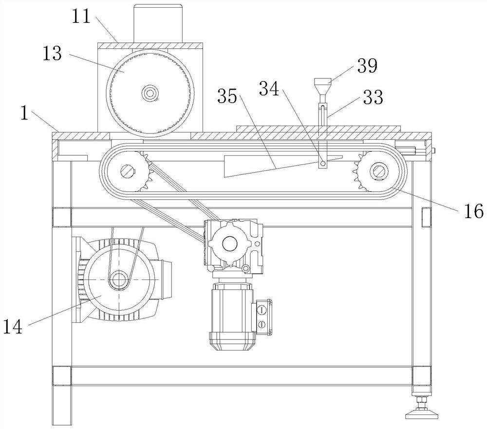
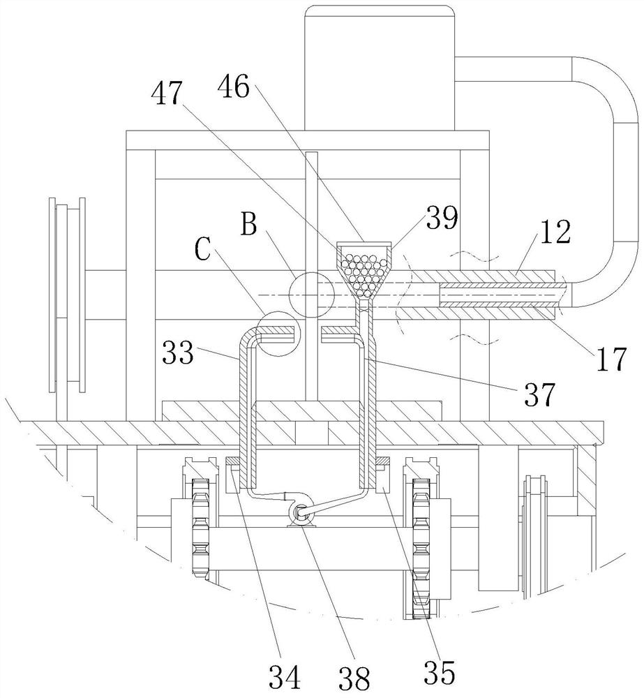
[0031] Such as Figure 1 to Figure 6As shown, a kind of magnetic steel production equipment for motors according to the present invention includes a workbench 1; the top of the workbench 1 is connected to a rotating shaft 12 through a bracket 11, and a cutting blade 13 is fixedly connected to the middle of the rotating shaft 12; A main motor 14 is fixedly connected to the bottom of the table 1 and the corresponding position of the rotating shaft 12, and the main motor 14 drives the rotating shaft 12 to rotate through a belt; the top of the workbench 1 is provided with a slide plate 15 on the side away from the support 11, and the bottom of the slide plate 15 is provided with a horizontal movement unit 16. A clamping unit is provided on the top of the slide plate 15; the rotating shaft 12 is hollow, and an air pipe 17 is sleeved inside the rotating shaft 12, and the air pipe 17 is connected to the rotating shaft 12 in a rotating and sealed manner; Box 18 is communicated with tr...

Embodiment 2

[0040] Such as Figure 7 As shown, a cavity 41 is provided in the sealing strip 4; an ejector cylinder 42 is slidably connected to the water channel 36 at the top of the gripper 33, and the cross section of the ejector cylinder 42 is U-shaped, and the ejector cylinder 42 is connected to the The water channel 36 is in sliding and sealed connection; the end of the ejector cylinder 42 close to the interior of the water channel 36 is provided with a cylinder 43, the fixed end of the cylinder 43 is fixedly connected with the inner wall of the water channel 36, and the piston rod 44 of the cylinder 43 is fixedly connected with the ejector tube 42 The cylinder 43 communicates with the cavity 41 through the pipeline; the compressed air generated in the cavity 41 is charged into the cylinder 43 through the pipeline when the sealing strip 4 is squeezed, so that the piston rod 44 stretches out and pushes the ejector cylinder 42, The ejector tubes 42 at the top of the two grippers 33 are ...


PUM


Abstract

The invention belongs to the technical field of magnetic steel processing devices, and is specifically a kind of magnetic steel production equipment for motors, including a workbench; The motor is fixedly connected to the corresponding position, and the motor drives the rotating shaft to rotate through the belt; the top of the workbench is equipped with a slide plate on the side away from the support, the bottom of the slide plate is equipped with a horizontal moving unit, and the top of the slide plate is equipped with a clamping unit; the rotating shaft is hollow, and the inner sleeve of the rotating shaft There is an air pipe, and the air pipe is connected to the rotating shaft in a sealed manner; a refrigeration box is fixedly connected to the top of the bracket, and the refrigeration box is connected to the air pipe; a group of air injection holes are evenly distributed on the side of the cutting piece along the radial direction of the cutting piece; the air injection holes communicate with the air pipe through the communication hole; The cooling gas is sent into the hollow rotating shaft through the air pipe, and then sprayed out from the gas injection hole after passing through the communication hole, which reduces the heating of the magnetic steel sheet during the cutting process and increases the property stability of the magnetic steel sheet after cutting.

Description

technical field [0001] The invention belongs to the technical field of magnet steel processing devices, in particular to a magnet steel production equipment for motors. Background technique [0002] Magnetic steel generally refers to AlNiCo alloy. Magnetic steel is composed of several hard and strong metals, such as iron and aluminum, nickel, cobalt, etc., sometimes copper, niobium, and tantalum. It is used to make superhard permanent magnetic alloys. The production process of magnetic steel mainly includes raw material crushing, mixing, passivation treatment, pressing forming, sintering and cutting forming. [0003] In the prior art, there are also some technical solutions for magnetic steel processing devices. For example, a Chinese patent with application number 2018218350766 discloses a square magnetic steel production equipment that is not easy to demagnetize, including a workbench. A chute is provided symmetrically on the side, and a slide block is slidably connected ...

Claims


Application Information

Patent Timeline
Patent Type & Authority Patents(China)
IPC IPC(8): H02K15/03
CPCH02K15/03
Inventor 宋芳
Owner 徐州给力磁业有限公司
Why Eureka
Try Eureka