

Slag removal anti-lock braking system for rock tube push bench and slag removal method
An anti-lock braking system and pipe jacking machine technology, which is used in earth-moving drilling, mining equipment, tunnels, etc., can solve problems such as line construction failure, tool pipe cutter head stuck, and anti-corrosion layer easily scratched, etc. Accuracy, the effect of reducing the frequency of slag cleaning
- Summary
- Abstract
- Description
- Claims
- Application Information
AI Technical Summary
Problems solved by technology
Method used
Image

Examples
Embodiment Construction
[0032] specific implementation plan
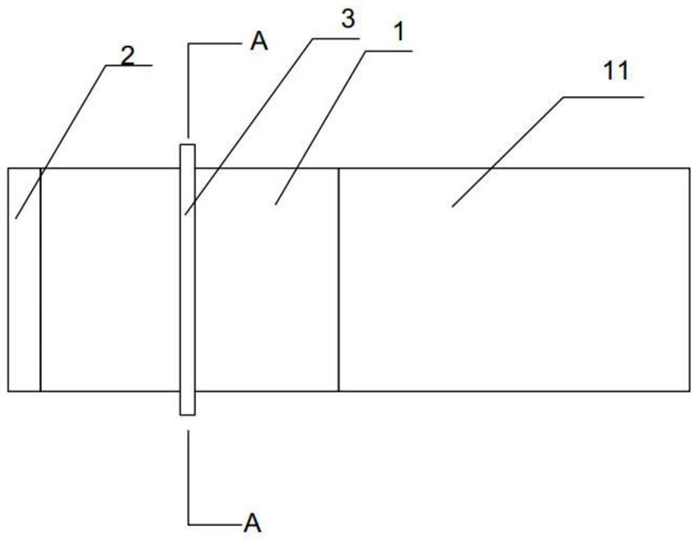
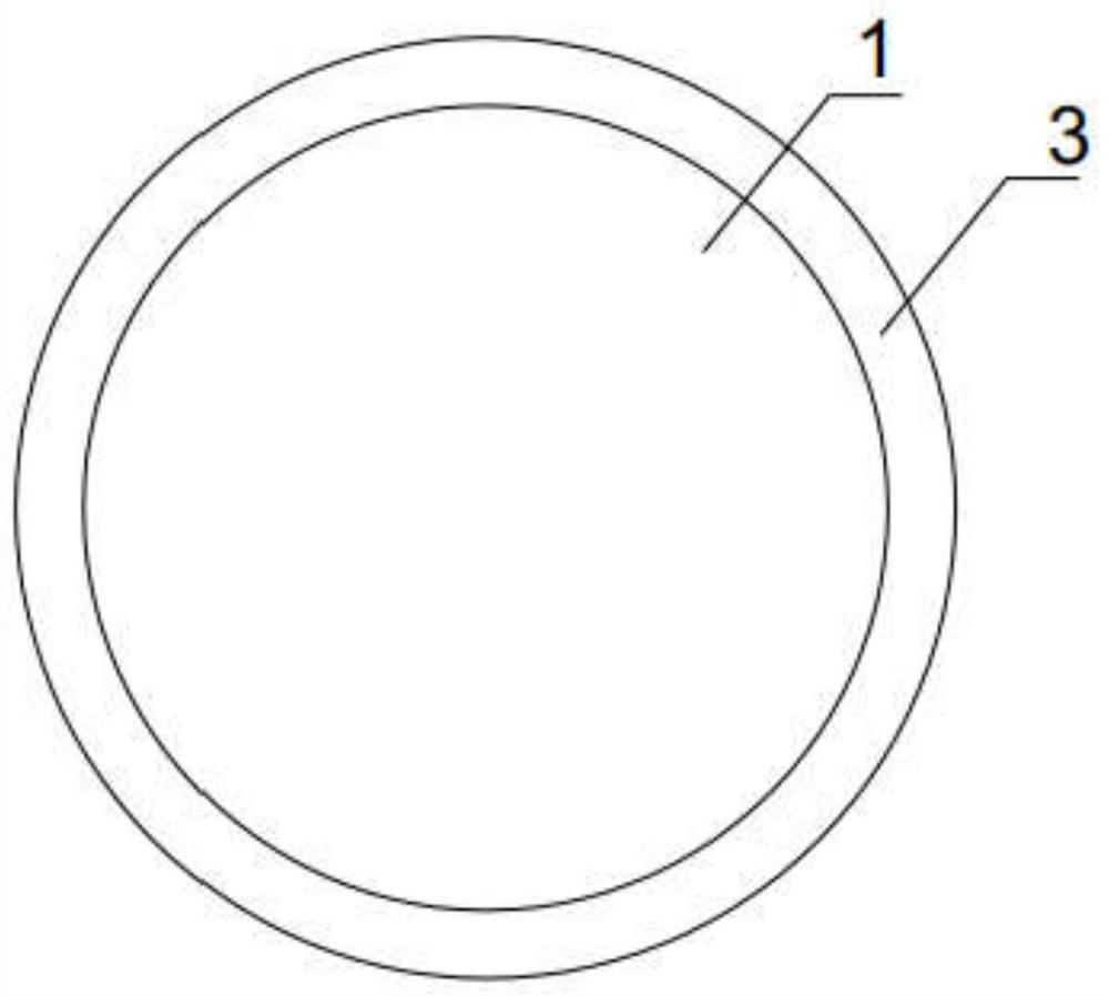
[0033] Such as figure 1 , 2 Among them, an anti-lock braking system for a rock pipe jacking machine, the pipe jacking machine includes a tool pipe 1 provided with a drill bit 2 and a matching pipe 11 connected to the tool pipe 1, and the anti-lock braking system includes The slag retaining plate 3 arranged on the tool pipe 1;
[0034] The slag retaining plate 3 can prevent mud and / or sand and / or stones from flowing along the outer wall of the tool pipe 1 into the rear end of the tool pipe 1, thereby avoiding the accumulation of a large amount of sand and / or sand at the rear end of the tool pipe 1 The stones cause the rear end of the tool pipe 1 to be stuck in the rock. Preferably, the slag retaining plate 3 is arranged transversely along the wall of the tool pipe 1 , that is, the slag retaining plate 3 surrounds the tool pipe 1 for a week.
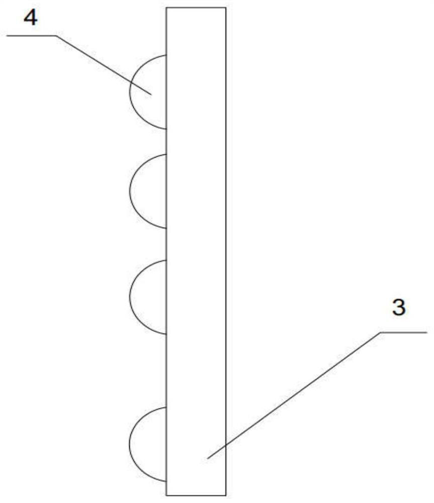
[0035] Such as image 3 Among them, the surface of the slag retaining plate 3 is provided with ...
PUM
 Abstract
Description
Claims
Application Information