
Grid mesh type fiber bragg grating acceleration geophone

A technology of geophones and fiber gratings, applied in seismic signal receivers, seismology, instruments, etc., can solve the problems of difficult prestressed packaging and the influence of geophone boundary conditions, etc., so as to enhance the lateral anti-interference ability and improve the comprehensive Responsive, easy-to-package effects

Pending Publication Date: 2021-08-31
XI'AN PETROLEUM UNIVERSITY
View PDF0 Cites 2 Cited by
  • Summary
  • Abstract
  • Description
  • Claims
  • Application Information

AI Technical Summary

Problems solved by technology

[0005] The purpose of the present invention is to provide a grid-type fiber grating acceleration geophone to solve the technical problems that the boundary conditions of the geophone affect the stability and the difficulty of prestressed packaging

Method used


Image

  • Grid mesh type fiber bragg grating acceleration geophone
  • Grid mesh type fiber bragg grating acceleration geophone
  • Grid mesh type fiber bragg grating acceleration geophone

Examples


Embodiment 1

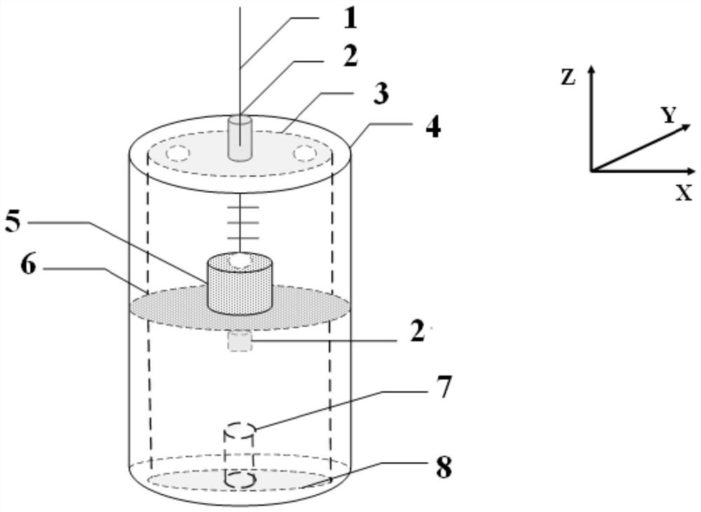
[0027] see figure 1 As shown, a grid-type fiber grating acceleration geophone of the present invention mainly consists of a fiber grating 1, a capillary 2, an upper top cover 3, a metal shell 4, an inertial mass 5, a grid sensitive structure 6, a fixing seat 7, Lower bottom 8 (including 7).

[0028] The inertial mass 5 shown has a blind hole in the center of the upper and lower end faces, and is connected with the sensitive structure of the grid through a capillary with an external thread, and is fixed by a nut.

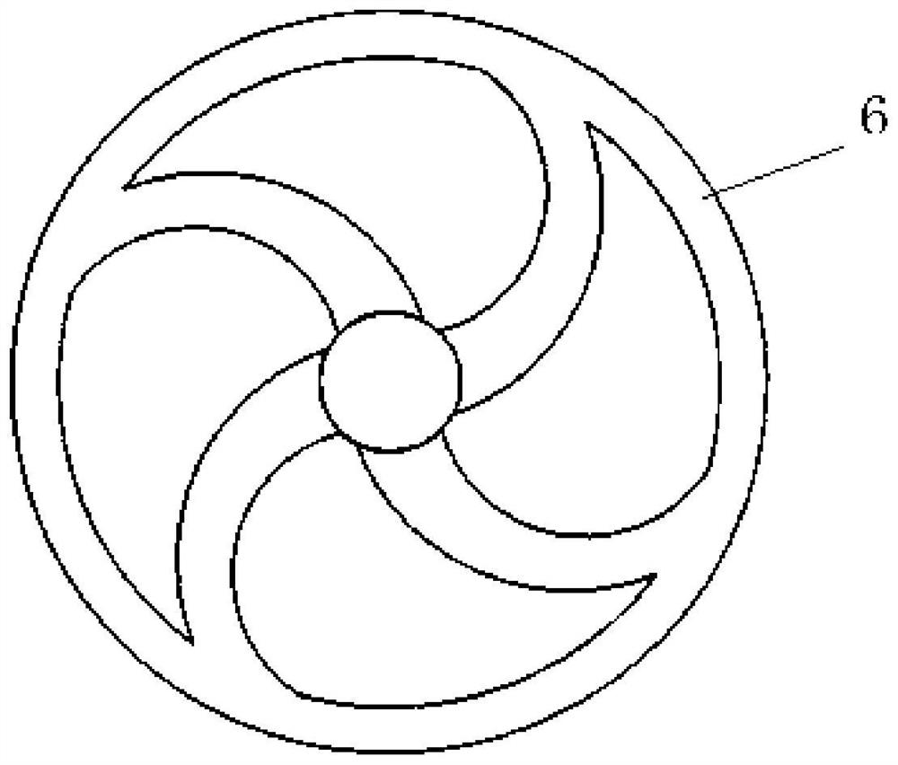
[0029] The grid-sensitive structure described, section reference figure 2 .

[0030] Described metal shell 4, inner wall (including screw thread) is provided with boss;

[0031] Both the upper top cover 3 and the lower bottom 8 can be screwed into the inner wall of the metal casing 4, and after being screwed in, they are level with the edge height of the metal casing, and the lower bottom 8 is provided with a fixed base 7.

[0032] The capillary 2 is screwed int...

Embodiment 2

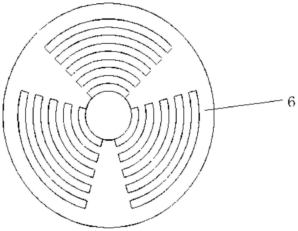
[0038] In this embodiment, the component parameters and materials of the geophone are the same as in Embodiment 1, the difference is that the grid-type sensitive structure such as image 3 As shown, the thickness is also 0.1mm, the outer radius is also 16mm, the distance of the center "hollowout" is the same, and the radius of the hard core is also 3mm. The other components and the connection relationship of the components are the same as in Embodiment 1.

Embodiment 3

[0040] In this embodiment, the component parameters and materials of the geophone are the same as those in Embodiment 1 and Embodiment 2, the difference is that the fiber grating 1 is replaced by double FBGs, the center wavelengths are respectively 1548.353nm and 1552.017nm, and the edge film The suppression ratios are 16dB and 15dB respectively, the bandwidths are 0.210nm and 0.218nm respectively, the geometric lengths of the grid regions are 10mm and 10mm respectively, and the reflectivity are 91.09% and 92.02% respectively. The double fiber gratings are respectively fixed on the top cover 3 of the geophone and the "grid-type" sensitive structure 6 (including the connection point with the inertial mass block), the "grid-type" sensitive structure and the threaded capillary, and other parts And the connection relationship of parts is the same as that of Embodiment 1.


PUM

PropertyMeasurementUnit
Center wavelengthaaaaaaaaaa
Thicknessaaaaaaaaaa
Outer radiusaaaaaaaaaa

Abstract

A grid mesh type fiber bragg grating acceleration geophone comprises a fiber bragg grating, a capillary tube, a shell, an inertial mass block and a grid mesh type sensitive structure; the capillary tube is arranged in the center of the top of the shell and communicated with the interior of the shell; a boss is arranged on the inner side wall of the shell, the grid mesh type sensitive structure is erected on the boss, and the inertial mass block is arranged in the center of the grid mesh type sensitive structure; and the fiber bragg grating sequentially penetrates through the capillary tube and the inertial mass block to be connected to the grid mesh type sensitive structure, and the fiber bragg grating is connected with an external demodulation unit. According to the sensing principle that the central wavelength drifts after the fiber bragg grating is subjected to external strain, the inertia mass block of the detector generates inertia force under the excitation of external vibration signals. Under the action of inertia force, the grid mesh sensitive structure generates axial strain, so that the central wavelength of the fiber bragg grating packaged on the grid mesh sensitive structure drifts, the change of the central wavelength is detected by virtue of a demodulation system, the detection of seismic wave signals is realized, and meanwhile, the capability of transverse cross interference can also be enhanced.

Description

technical field [0001] The invention belongs to the technical field of optical fiber sensing, in particular to a grid-type optical fiber grating acceleration geophone. Background technique [0002] As a wavelength-based optical fiber device, fiber Bragg grating has made great progress in the research direction of optical communication and optical sensing. In particular, the research direction of optical sensing has attracted widespread attention in many application fields, mainly due to its unique advantages. Compared with traditional electrical geophones, it has the advantages of anti-electromagnetic interference and small size; compared with intensity-type optical fiber sensors, it is not affected by light source fluctuations and is conducive to wavelength division multiplexing; compared with phase-type optical fiber sensors, The device has the advantages of simple components, small volume, and good reuse; compared with the polarization optical fiber sensor, it is easy to ...

Claims


Application Information

Patent Timeline
IPC IPC(8): G01V1/18
CPCG01V1/181
Inventor 刘钦朋刘望飞高宏禹大宽王春芳张蓉
Owner XI'AN PETROLEUM UNIVERSITY
Learn More