Control method and system for deadbeat current prediction of position sensorless permanent magnet motor

A permanent magnet motor, current prediction technology, applied in control systems, motor control, vector control systems, etc., can solve the problems of system size, weight, high maintenance cost, low current prediction accuracy, etc., to solve the problems of phase lag, sensitive The effect of reducing the stability and improving the robustness of the system

Active Publication Date: 2022-02-15
HARBIN INST OF TECH
View PDF5 Cites 0 Cited by
  • Summary
  • Abstract
  • Description
  • Claims
  • Application Information

AI Technical Summary

Problems solved by technology

[0005] The purpose of the present invention is to solve the problems of large size and weight of the system, high maintenance cost, and low accuracy of current prediction when the motor parameters change in the existing deadbeat current prediction method, and proposes a deadbeat current prediction method. Control method and system for deadbeat current prediction of position sensor permanent magnet motor

Method used


Image

  • Control method and system for deadbeat current prediction of position sensorless permanent magnet motor
  • Control method and system for deadbeat current prediction of position sensorless permanent magnet motor
  • Control method and system for deadbeat current prediction of position sensorless permanent magnet motor

Examples


specific Embodiment approach 1

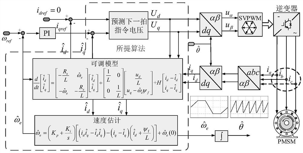
[0057] Specific implementation mode 1. Combination figure 1 This embodiment will be described. A control method for deadbeat current prediction of a position sensorless permanent magnet motor described in this embodiment, the method specifically includes the following steps:

[0058] Step 1. Rewrite the stator voltage flux equation in the motor rotating coordinate system into the stator current form, and use the stator current form equation as a reference model, and use the deadbeat current prediction equation including the feedback gain matrix as an adjustable model, and Build an adaptive observer according to the reference model and the adjustable model;

[0059] Step 2, based on the adaptive observer constructed in step 1, obtain the estimated values ​​of the rotor electrical angular velocity and the rotor position angle;

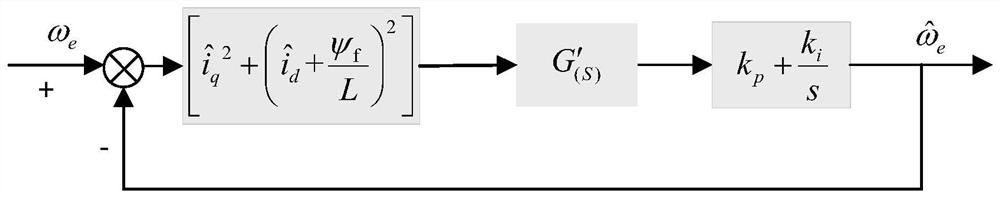
[0060] Using the estimated value of the rotor electrical angular velocity, the rotor electrical angular velocity estimation process is sorted into a s...

specific Embodiment approach 2

[0066] Specific embodiment two: the difference between this embodiment and specific embodiment one is that in the first step, the stator voltage flux equation under the motor rotating coordinate system is rewritten into the stator current form, and the specific process is as follows:

[0067] The expression of the stator voltage flux equation is shown in formula (1):

[0068]

[0069] Among them: u d is the actual stator voltage in the d-axis coordinate system, u q is the actual stator voltage in the q-axis coordinate system; i d is the actual stator current in the d-axis coordinate system, i q is the actual stator current in the q-axis coordinate system; R s is the stator resistance; L d is the inductance in the d-axis coordinate system, L q is the inductance in the q-axis coordinate system; ψ d is the stator flux linkage in the d-axis coordinate system, ψ q is the stator flux linkage in the q-axis coordinate system; ω e is the rotor electrical angular velocity; ψ ...

specific Embodiment approach 3

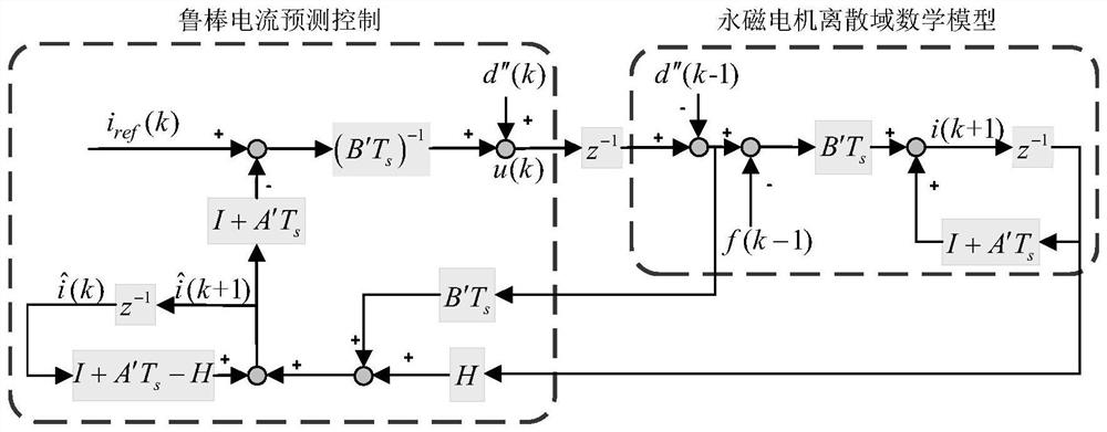
[0076] Embodiment 3: This embodiment is different from Embodiment 2 in that the deadbeat current prediction equation including the feedback gain matrix is:

[0077]

[0078] where: i, are the actual stator current and the estimated stator current respectively, d″ is the back EMF vector of the adjustable model, A′ and B′ are the state matrix coefficients of the adjustable model, H is the feedback gain matrix;

[0079] The expression of the state matrix coefficient A', B' of the adjustable model is: A'=-a' 1 I+a' 2 J,B'=b 1 I, a' 1 = R s / L, is the estimated value of the rotor electrical angular velocity; the expression of the feedback gain matrix H is: H=h 1 I+h 2 J, h 1 and h 2 is the feedback gain matrix parameter; the estimated stator current The expression is is the estimated stator current in the d-axis coordinate system, is the estimated stator current in the q-axis coordinate system, and the expression of the back EMF vector d″ of the adjustable m...


PUM


Abstract

The invention discloses a control method and system for deadbeat current prediction of a permanent magnet motor without a position sensor, belonging to the technical field of motor control. The invention solves the problems of large size and weight of the system, high maintenance cost and low current prediction accuracy when motor parameters change in the existing deadbeat current prediction method. The present invention uses the deadbeat current prediction equation including the feedback gain matrix as an adjustable model, constructs a new adaptive observer, and deduces the conditions that can ensure the stability of the system according to Popov's super-stability theory; not only the adjustable The model predicts the command voltage of the next sampling cycle to improve the dynamic performance of the system, and by increasing the feedback gain, the stable area of ​​the estimated speed and position angle information is improved, and the robustness of the system is improved. Combining dead-beat current prediction and position sensorless control into one observer form simplifies the motor control algorithm. The invention can be applied to the control of deadbeat current prediction.

Description

technical field [0001] The invention belongs to the technical field of motor control, and in particular relates to a control method and system for deadbeat current prediction of a position sensorless permanent magnet motor. Background technique [0002] Permanent magnet synchronous motors have been widely used and continuously developed in the field of AC motor speed control systems due to their significant advantages such as simple structure, reliable operation, light weight, high efficiency, and high power-to-weight ratio. Compared to DC motors, it has no commutator and brushes, thus reducing maintenance cost and possible inconvenience. Compared with the asynchronous motor, the structure is relatively simple, the stator current and stator resistance loss are reduced, the rotor parameters can be measured, and the control performance is good. Compared with ordinary synchronous motors, it saves the excitation device, simplifies the structure and improves the efficiency. Wit...

Claims


Application Information

Patent Timeline
Patent Type & Authority Patents(China)
IPC IPC(8): H02P21/28H02P21/22H02P21/13H02P21/18H02P21/00H02P25/024H02P27/12
CPCH02P21/28H02P21/22H02P21/13H02P21/18H02P21/0003H02P21/0017H02P25/024H02P27/12H02P2207/05
Inventor 王勃云志鹏于泳徐殿国
Owner HARBIN INST OF TECH
Why Eureka
Try Eureka