High-linearity transconductance circuit

A high-linearity, circuit technology, applied in the direction of DC-coupled DC amplifiers, differential amplifiers, etc., can solve problems such as impact cancellation, difficulty in realizing broadband power matching, and inability to inject, so as to improve the offset effect, improve anti-interference performance, and improve performance. Effect

Active Publication Date: 2021-08-31
SHANGHAI CHIPANALOG MICROELECTRONICS LTD
View PDF7 Cites 1 Cited by
  • Summary
  • Abstract
  • Description
  • Claims
  • Application Information

AI Technical Summary

Problems solved by technology

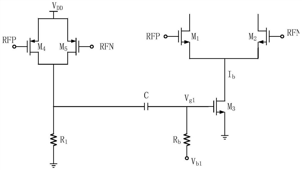
[0006] There are three deficiencies in this circuit structure: (1) IM 2 by C and R b AC coupled to M 3 tube gate, resulting in low frequency IM 2 item could not be injected
That is, when the frequency difference of the input dual tone is small, the IM generated by it 3 Items cannot be offset; (2) C and R b The resulting high-pass filter introduces additional phase shift, affecting the IM 3 Offset; (3)M 1 and M 2 The tube adopts grid input, it is difficult to achieve broadband power matching

Method used


Image

  • High-linearity transconductance circuit
  • High-linearity transconductance circuit
  • High-linearity transconductance circuit

Examples


Embodiment Construction

[0027] Embodiments of the present disclosure will be described in detail below in conjunction with the accompanying drawings.

[0028] Embodiments of the present disclosure are described below through specific examples, and those skilled in the art can easily understand other advantages and effects of the present disclosure from the contents disclosed in this specification. Apparently, the described embodiments are only some of the embodiments of the present disclosure, not all of them. The present disclosure can also be implemented or applied through different specific implementation modes, and various modifications or changes can be made to the details in this specification based on different viewpoints and applications without departing from the spirit of the present disclosure. It should be noted that, in the case of no conflict, the following embodiments and features in the embodiments can be combined with each other. Based on the embodiments in the present disclosure, a...


PUM


Abstract

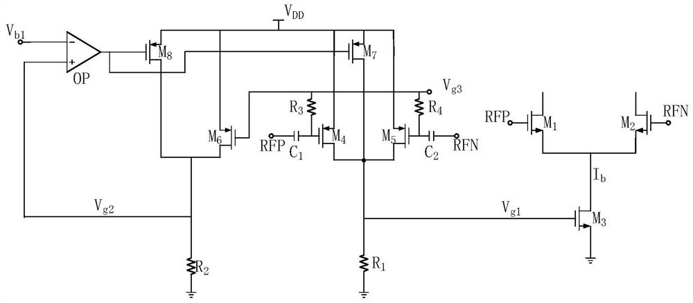
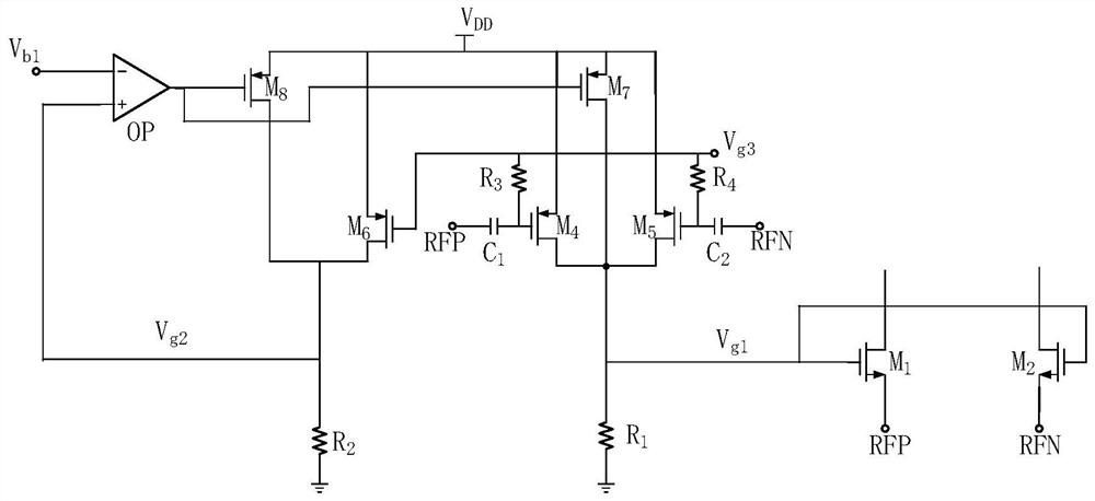
The invention provides a high-linearity transconductance circuit, and the circuit comprises a differential input stage circuit which converts an input voltage signal into a current signal; an IM2 injection circuit which is used for realizing direct current coupling injection of IM2 and comprises a first PMOS transistor M4, a second PMOS transistor M5, a third PMOS transistor M7 and a first resistor R1, wherein the feedback loop is used for forming negative feedback and comprises a fourth PMOS transistor M6, a fifth PMOS transistor M8, a second resistor R2 and an operational amplifier OP. According to the invention, IM2 direct current injection is adopted, so that the frequency interval of the double Tones can be expanded to be near the direct current, the injection position of the IM2 is changed from the grid electrode of the tail current tube to the grid electrode of the common-grid input differential pair tube, the IM3 item offset effect is obviously improved, the IIP3 performance of the circuit is greatly improved, and the anti-interference performance of the receiver is improved.

Description

technical field [0001] The present disclosure relates to the technical field of integrated circuits, in particular to a high linear transconductance circuit. Background technique [0002] In wireless receiving applications, the input RF signal is often accompanied by large interfering signals. These interference signals will eventually affect the normal reception of the target signal through the nonlinear effect of the receiving channel. [0003] When two adjacent interferences pass through a nonlinear system, the output will contain some components that do not belong to the harmonics of the input frequency, which is called intermodulation (IM). The intermodulation term produced by the second-order nonlinearity is called the second-order intermodulation term (IM 2 ); the intermodulation term generated by the third-order nonlinearity is called the third-order intermodulation term (IM 3 ). [0004] Third-order intermodulation (IM 3 ) is often the most common and serious i...

Claims


Application Information

Patent Timeline
Patent Type & Authority Applications(China)
IPC IPC(8): H03F3/45
CPCH03F3/45
Inventor 孙文恽廷华杨峰
Owner SHANGHAI CHIPANALOG MICROELECTRONICS LTD
Why Eureka
Try Eureka