Planar embedded annular structure and manufacturing process thereof

A ring-shaped structure and planar embedded technology, applied in water/sludge/sewage treatment, chemical instruments and methods, sludge treatment, etc., can solve the problems of low utilization rate of raw materials, large heat input, low yield, etc. Achieve the effect of small deformation of workpiece, prevent oxidation and improve utilization rate

Active Publication Date: 2021-09-03
成都环能德美环保装备制造有限公司
View PDF21 Cites 1 Cited by
  • Summary
  • Abstract
  • Description
  • Claims
  • Application Information

AI Technical Summary

Problems solved by technology

[0003] In the manufacturing and production of the stacked screw dehydrator, in order to ensure the smooth flow of the filtrate from the stacked screw body, the flatness of the fixed ring and the floating ring in the stacked screw body must be less than 0.3mm. The following two methods are usually used in the manufacturing process of the ring. The first one is to cut the stainless steel sheet in a one-time forming method to directly form the fixed ring and the floating ring. In this method, the process is simple and it is easy to control the fixed ring and the floating ring. The flatness of the ring, however, the raw material utilization rate is low, the consumables are large, and the material utilization rate is usually 13.34% to 18.23%, such as Figure 8 As shown; the second one is to cut the fixed ring and the moving ring into sections and then splice and assemble them, and finally fix them by welding to form a ring structure. Pressure resistance, this method requires full penetration of the weld seam, and the large heat input in the welding process can easily lead to deformation; resulting in low yield

Method used


Image

  • Planar embedded annular structure and manufacturing process thereof
  • Planar embedded annular structure and manufacturing process thereof
  • Planar embedded annular structure and manufacturing process thereof

Examples


Embodiment 1

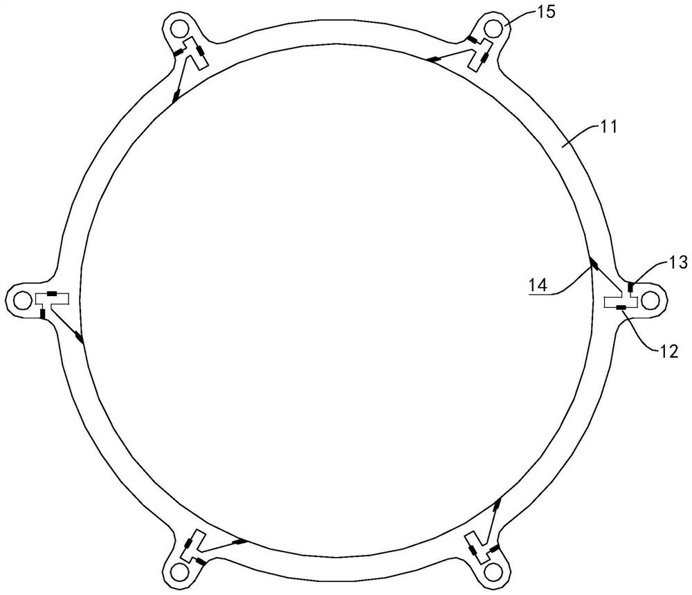
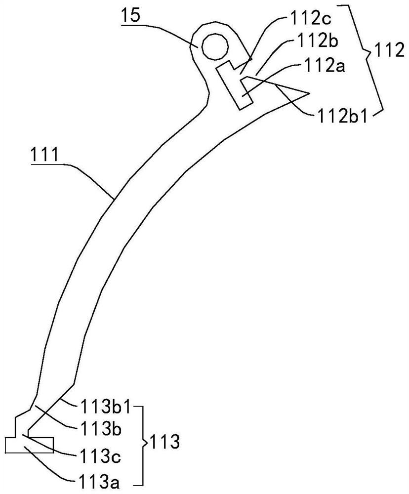
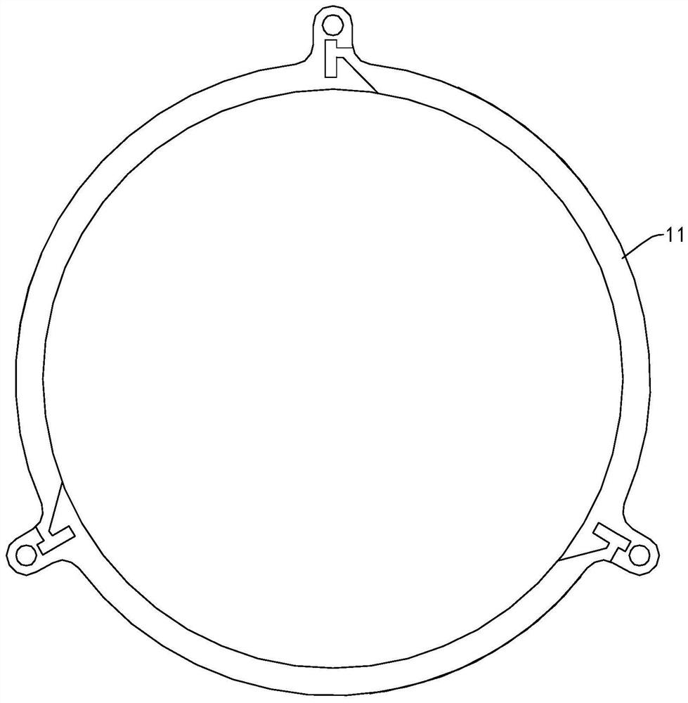
[0047] Please refer to Figure 1 to Figure 2 , the present embodiment provides a planar embedded annular structure, including several arc segment units 11, and several arc segment units 11 are sequentially connected end to end to form an annular structure, and the arc segment unit 11 includes an arc segment main body 111, and the arc segment units 11 One end of the section main body 111 is configured with a special-shaped splicing interface 112, and the other end of the arc section main body 111 is equipped with a special-shaped splicing block 113 that matches the special-shaped splicing interface 112. The special-shaped splicing block parts 113 are spliced ​​together, and several welding points are provided at the splicing points for welding the special-shaped splicing part 112 and the special-shaped splicing block part 113 at the welding points. Through the special-shaped splicing part 112 and the special-shaped splicing block part 113, since the special-shaped splicing part...


PUM


Abstract

The invention provides a plane embedded annular structure and a manufacturing process thereof. The plane embedded type annular structure comprises a plurality of arc section units, wherein the arc section units are sequentially connected end to end to form the annular structure, each arc section unit comprises an arc section main body, one end of each arc section main body is provided with a special-shaped splicing opening part, the other end of each arc section main body is provided with a special-shaped splicing block part matched with the corresponding special-shaped splicing opening part, the special-shaped splicing opening parts and the special-shaped splicing block parts of the adjacent arc section units are spliced, and a plurality of welding points are arranged at the splicing positions of the special-shaped splicing opening parts and the special-shaped splicing block parts, so that the special-shaped splicing opening parts and the special-shaped splicing block parts can be welded at the welding points. The invention discloses a manufacturing process of a plane embedded type annular structure. The manufacturing process comprises the steps of raw material detection, plate flattening, nesting programming, cutting, product inspection, splicing assembly, laser welding and product flattening. According to the invention, the utilization rate of raw materials is increased, the precision and planeness required by the annular structure in the spiral dehydrator are guaranteed, and the stability is high.

Description

technical field [0001] The invention relates to the field of production and manufacturing of screw stacking dehydrators, in particular to a planar embedded ring structure and its manufacturing process. Background technique [0002] Screw stacking dewatering machine is a common sludge dewatering equipment, which has the characteristics of small footprint and large amount of sludge treatment, and is widely used in sludge in various industries such as municipal sewage, food and beverage, slaughtering and breeding, printing and dyeing, petrochemical, papermaking, etc. dehydration. The working principle of the stacked screw dehydrator is that the fixed ring and the swimming ring are interlaced to form a stacked screw body, and the screw shaft runs through the stacked screw body to form a filtering and pushing device. The front end is the concentration part, and the back end is the dehydration part. The filter slit formed between the rings and the pitch of the screw shaft gradual...

Claims


Application Information

Patent Timeline
Patent Type & Authority Applications(China)
IPC IPC(8): C02F11/125B23P15/00
CPCC02F11/125B23P15/00
Inventor 袁建强李海琼刘文武张福龙
Owner 成都环能德美环保装备制造有限公司
Why Eureka
Try Eureka