Biomass boiler feeding system

A biomass boiler and feeding system technology, which is applied in the directions of fuel supply, solid fuel combustion, and fuel supply regulation, etc., can solve the problem of broken shaft without shaft screw, the inability of the unit to achieve long-term operation, and the material blocking of the feeding system, etc. question

Pending Publication Date: 2021-09-03
黑龙江华热能源有限公司
View PDF0 Cites 0 Cited by
  • Summary
  • Abstract
  • Description
  • Claims
  • Application Information

AI Technical Summary

Problems solved by technology

[0025] The research and development purpose of the present invention is to solve the problems of blockage, shaft breakage and shaftless screw breakage in the feed system in front of the furnace of power plants in the current biomass industry, which cause the unit to fail to achieve long-term operation. A brief overview of the present invention is given below, in order to provide a basic understanding of certain aspects of the invention

Method used


Image

  • Biomass boiler feeding system

Examples


specific Embodiment approach 1

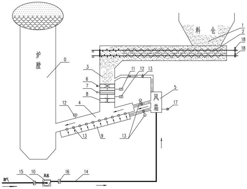
[0046] Specific implementation mode one: combine figure 1 Describe this embodiment, a biomass boiler feeding system of this embodiment, including a feed bin 1, a secondary screw feeder 2, a feed pipe 3, a drop pipe 4, a bellows 5, and a pneumatic quick shut-off valve 6 , heavy hammer lever valve 7, metal expansion joint 8, fluidization wind bellows 9 and fan 10, the bottom of silo 1 is connected and installed with secondary screw feeder 2, and secondary screw feeder 2 is connected with feeding pipe 3 Connecting and matching installation, feeding pipe 3 and feeding pipe 4 are connected and installed, feeding pipe 4 is connected and installed with furnace 0, bellows 5 are respectively connected and installed with feeding pipe 3 and feeding pipe 4, feeding pipe 3 is connected and installed from Pneumatic quick shut-off valve 6, heavy hammer lever valve 7 and metal expansion joint 8 are installed sequentially from top to bottom. Fluidization wind bellows 9 are installed on the bot...

specific Embodiment approach 2

[0054] Specific implementation mode two: combination figure 1 Describe this embodiment, a biomass boiler feeding system of this embodiment, a pressure sensor 11 is installed on the feed pipe 3 between the pneumatic quick shut-off valve 6 and the weight lever valve 7 .

specific Embodiment approach 3

[0055] Specific implementation mode three: combination figure 1 Describe this embodiment, a biomass boiler feeding system of this embodiment, a pressure sensor 11 is installed on the feed pipe 3 between the pneumatic quick shut-off valve 6 and the weight lever valve 7 .


PUM


Abstract

The invention discloses a biomass boiler feeding system, and belongs to the field of biomass boilers. According to the biomass boiler feeding system, the bottom of a stock bin and a secondary spiral feeder are installed in a communicating and matched mode, the secondary spiral feeder and a feeding pipe are installed in a communicating and matched mode, the feeding pipe and a discharging pipe are installed in a communicating and matched mode, the discharging pipe and a hearth are installed in a communicating and matched mode, an air bellow is installed in a communicating and matched mode with the feeding pipe and the discharging pipe, a pneumatic quick shut-off valve, a heavy hammer type lever valve and a metal expansion joint are sequentially installed on the feeding pipe in a matched mode from top to bottom, a fluidization air bellow is installed at the bottom of the discharging pipe in a matched mode, the fluidization air bellow and an air bellow communicate and are installed in a matched mode, and the air bellow and a draught fan are installed in a matched mode. The biomass boiler feeding system aims to solve the problem that a unit cannot run for a long period due to material blockage, shaft breakage and shaftless spiral breakage of a stokehole feeding system of a power plant in the current biomass industry, reduce the labor intensity of operators, save electricity and reduce the production cost, the one-time investment cost, the repeated investment cost and the maintenance cost are saved, and meanwhile the target of long-period operation of the unit is achieved.

Description

technical field [0001] The invention relates to a biomass boiler feeding system, which belongs to the field of biomass boilers. Background technique [0002] At the end of 2019, my country's biomass power generation installed capacity reached 22.54 million KWH, a year-on-year increase of 26.6%; biomass power generation capacity was 1,111.1 billion KWH, a year-on-year increase of 20.4%. As of the end of 2019, among all kinds of biomass energy, the installed capacity of waste incineration power generation accounted for 53% of the total installed capacity of biomass power generation, ranking first; the installed capacity of agricultural and forestry waste power generation accounted for 43%; the installed capacity of biogas power generation accounted for 4%. If 43% of the 22.54 million KWH of biomass installed capacity is calculated as an average of 30,000 boilers, there are about 323 agricultural and forestry waste biomass boilers. [0003] However, the layout of the feeder i...

Claims


Application Information

Patent Timeline
Patent Type & Authority Applications(China)
IPC IPC(8): F23K3/02F23K3/14F23B80/02F23N1/00
CPCF23K3/02F23K3/14F23B80/02F23N1/005
Inventor 曾其刚
Owner 黑龙江华热能源有限公司
Why Eureka
Try Eureka