Separation device and separation method for preventing coking at bottom of catalytic depropanization tower

A technology of depropanizer tower and depropanizer tower, which is applied in the field of separation device to prevent coking at the bottom of catalytic depropanizer tower, and can solve problems such as increased production and operation costs

Pending Publication Date: 2021-09-07
BEIJING OUYIDE TECH +2
View PDF8 Cites 0 Cited by
  • Summary
  • Abstract
  • Description
  • Claims
  • Application Information

AI Technical Summary

Problems solved by technology

Injecting a polymerization inhibitor can relieve the problem of coking and clogging at the bottom of the depropanizer to a certain extent, but it cannot fundame

Method used


Image

  • Separation device and separation method for preventing coking at bottom of catalytic depropanization tower

Examples


Embodiment 1

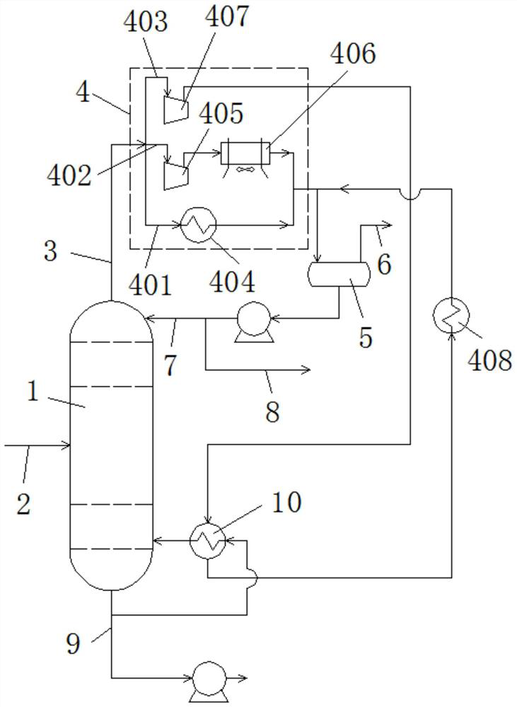
[0048] In this embodiment, the depropanizer 1 has 30 theoretical plates, the operating pressure at the top of the tower is 0.85 MPag, the temperature at the top of the tower is 16°C, and the temperature at the bottom of the tower is 74.3°C. The inlet line 2 is located above the tray 10 of the depropanizer 1 . The fuel gas is discharged directly to the flare. The tower top condensing mechanism 4 adopts mode 1, the gaseous phase material at the tower top is condensed by the condenser 404, and the condenser 404 uses 7°C refrigerant water as a cooling source. The bottom reboiler 10 uses 90°C hot water as a heat source.

[0049] The separation method includes the following steps:

[0050] The material from the upstream device enters the depropanizer 1 through the side line inlet pipeline 2; the gas phase material from the top of the depropanizer 1 is cooled by the top condenser 404 to form a condensate and enters the top reflux tank 5, and the condensate is pressurized by a pump ...

Embodiment 2

[0052] In this embodiment, the depropanizer 1 has 30 theoretical plates, the operating pressure at the top of the tower is 0.6 MPag, the temperature at the top of the tower is 6.5° C., and the temperature at the bottom of the tower is 63.3° C. The side inlet line 2 is located above the tray 10 of the depropanizer 1 . The tower top condensing mechanism 4 adopts the second method, the gas phase material at the top of the tower is pressurized to 1.7MPag by the first tower top gas booster 405, and then enters the cooler 406, and the cooler 406 is cooled by an air cooler. The bottom reboiler 10 uses 85°C hot water as a heat source.

[0053] The separation method includes the following steps:

[0054] The material from the upstream device enters the depropanizer 1 through the side line inlet pipeline 2; the gas phase material coming out of the top of the depropanizer 1 is pressurized by the first tower top gas booster 405, and then enters the cooler 406, and the air cooler is used ...

Embodiment 3

[0056] In this example, the depropanizer 1 has 30 theoretical plates, the operating pressure at the top of the tower is 0.65 MPag, the temperature at the top of the tower is 8.8°C, and the temperature at the bottom of the tower is 65.2°C. The side inlet line 2 is located at the 10th floor of the tray. The tower top condensing mechanism 4 adopts the third method. After the tower top gas phase is pressurized to 2.85 MPag by the second tower top gas booster 407, it enters the tower bottom reboiler 10, exchanges heat with the tower bottom material, and then passes through the tower top gas. After the cooler 408 is condensed, all condensate is formed and enters the top reflux tank 5 . The bottom reboiler 10 does not require an external heat source.

[0057] The separation method includes the following steps:

[0058] The material from the upstream device enters the depropanizer 1 through the side line inlet pipeline 2; the gas phase material coming out of the top of the depropani...


PUM


Abstract

The invention provides a separation device for preventing coking at the bottom of a catalytic depropanization tower. The device comprises a depropanization tower, an inlet pipeline is arranged in the middle of the depropanization tower, a tower top gas phase delivery pipeline is arranged at the top of the depropanization tower, and a tower top condensation mechanism and a tower top reflux tank are sequentially arranged on the tower top gas phase delivery pipeline along the gas phase flowing direction. According to the invention, a low-pressure depropanization process is adopted for separation, so that the operation temperature of the tower bottom is effectively reduced, the problem of coking and blocking at the bottom of the depropanization tower is fundamentally solved, and reduction of the processing load and non-planned shutdown of a catalytic gas separation device caused by the coking and blocking at the bottom of the depropanization tower are avoided; the temperature of the tower bottom is low, and a reboiler at the tower bottom can adopt hot water of 80-95 DEG C in a factory, waste heat of low-temperature process materials or low-pressure steam is used as a heat source, so that the steam consumption at the tower bottom of the depropanizing tower is saved, and the energy consumption of the device is reduced.

Description

technical field [0001] The invention relates to a separation device for low-pressure depropanization in a catalytic gas fractionation device, in particular to a separation device and a separation method for preventing coking at the bottom of a catalytic depropanizer. Background technique [0002] The gas fractionation unit is a supporting production unit for catalytic cracking and catalytic cracking. The main purpose is to recover and separate propylene and propane products in catalytic liquefied gas (liquid hydrocarbon). Due to its high severity, catalytic cracking has higher propylene yield and butadiene content than conventional catalytic cracking units. Liquid hydrocarbons produced by catalytic cracking and catalytic cracking units are sent to the downstream gas fractionation unit for fractionation after being processed by the refining unit (alkali washing, desulfurization, and sweetening). [0003] Catalytic gas fractionation devices at home and abroad are usually desi...

Claims


Application Information

Patent Timeline
IPC IPC(8): C07C7/04C07C9/08C07C11/06
CPCC07C7/04C07C9/08C07C11/06
Inventor 练弢毛存彪李网章蒋波李春晓练泽平陈振江要洁王仕文娄永峰高春杰成慧禹焦伟州
Owner BEIJING OUYIDE TECH
Why Eureka
Try Eureka