Gas turbine system based on main combustion area ammonia injection denitration and denitration method thereof

A gas turbine and main combustion zone technology, applied in gas turbine devices, turbine/propulsion fuel delivery systems, separation methods, etc., can solve problems such as high initial investment and operating costs, ammonia escape, etc., to improve the treatment effect, eliminate ammonia escape, Stable performance

Active Publication Date: 2021-09-07
XIAN THERMAL POWER RES INST CO LTD
View PDF8 Cites 0 Cited by
  • Summary
  • Abstract
  • Description
  • Claims
  • Application Information

AI Technical Summary

Problems solved by technology

Among them, the combustion process control is mainly to reduce the production of nitrogen oxides by reducing the combustion temperature or the residence time of natural gas in high-temperature areas, including water injection / steam injection technology in the combustion chamber, catalytic combustion technology, dry low-nitrogen combustion technology, etc. However, at present, the above technologies are mainly mastered by gas turbine main engine manufacturers; and the Selective Catalytic Reduction (SCR) technology is currently the most widely used and most effective flue gas denitrification technology, which can achieve a denitrification efficiency of more than 90%, but its initial investment and operation Higher cost and ammonia slip

Method used


Image

  • Gas turbine system based on main combustion area ammonia injection denitration and denitration method thereof

Examples


Embodiment Construction

[0032] The present invention will be further described in detail below in conjunction with specific embodiments, which are explanations of the present invention rather than limitations.

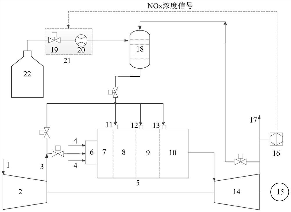
[0033] The present invention is a gas turbine system based on ammonia injection and denitrification in the main combustion zone, such as figure 1 Shown, comprise compressor 2, combustor 5, turbine 14, generator 15, ammonia supply device and flue gas analyzer 16;

[0034] The combustion chamber 5 is successively a combustion chamber head 7, a main combustion zone 8, a supplementary combustion zone 9, and a mixing zone 10 from front to back; the combustion chamber head 7 is provided with a burner 6; the main combustion chamber Zone 8 is evenly provided with more than 4 ammonia injection nozzles 11 around the wall surface, the supplementary combustion zone 9 is provided with supplementary combustion air nozzles 12, and a number of mixing holes 13 are provided on the wall surface of the mixing zo...


PUM


Abstract

The invention relates to a gas turbine flue gas denitration technology, in particular to a gas turbine system based on main combustion area ammonia injection denitration and a denitration method thereof. The gas turbine system comprises a combustion chamber, an ammonia gas supply device, a gas compressor, a turbine and a generator, wherein the ammonia gas supply device and the gas compressor are connected to the combustion chamber, and the turbine and the generator are connected to an outlet of the combustion chamber; the interior of the combustion chamber is sequentially divided into a combustion chamber head, a main combustion area, an afterburning area and a mixing area from front to back; a combustor is arranged at an inlet of the combustion chamber head; the combustor is further connected with a natural gas pipeline; an ammonia spraying nozzle is formed in the inner wall of the combustion chamber where the main combustion area is located; an afterburning air nozzle is formed in the inner wall of the combustion chamber where the afterburning area is located; a mixing hole is formed in the inner wall of the combustion chamber where the mixing area is located; a gas inlet of the ammonia gas supply device is connected with an exhaust gas outlet of the turbine, and a gas outlet of the ammonia gas supply device is connected with the ammonia spraying nozzle; and an outlet of the gas compressor is connected with the combustor, the afterburning air nozzle and the mixing hole through a high-temperature high-pressure air pipeline.

Description

technical field [0001] The invention relates to gas turbine flue gas denitration technology, in particular to a gas turbine system based on ammonia injection denitration in a main combustion zone and a denitration method thereof. Background technique [0002] Gas-fired power generation is characterized by cleanliness and high efficiency. In recent years, the installed capacity of gas-turbine power plants in my country has continued to expand, which has effectively promoted the transformation of my country's energy structure. Due to the technological characteristics of high combustion temperature and large excess air coefficient, gas turbine power plants produce a large amount of nitrogen oxides during the production process. Nitrogen oxides are one of the main causes of air pollution, photochemical smog, and acid rain. In recent years, my country's requirements for the emission limits of nitrogen oxides in the power generation industry have become more and more stringent. A...

Claims


Application Information

Patent Timeline
Patent Type & Authority Applications(China)
IPC IPC(8): F02C3/04F02C3/30F02C3/14F02C6/00F02C9/48H02K7/18B01D53/76B01D53/56
CPCF02C3/04F02C3/30F02C3/14F02C6/00F02C9/48H02K7/1823B01D53/76B01D53/56B01D2251/2062
Inventor 陆续张向宇吴庆龙张波向小凤徐宏杰
Owner XIAN THERMAL POWER RES INST CO LTD
Why Eureka
Try Eureka