Bioretention pond with deep denitrification function

A bioretention tank and denitrification technology, applied in the field of bioretention tank devices, can solve the problems of weak anoxic denitrification function, poor sustainable utilization effect, unstable nitrogen purification effect, etc.

Inactive Publication Date: 2021-09-10
TAIZHOU UNIV
View PDF0 Cites 0 Cited by
  • Summary
  • Abstract
  • Description
  • Claims
  • Application Information

AI Technical Summary

Problems solved by technology

However, the existing bioretention tank technology is not stable for nitrogen purification in rainwater, especially the removal of nitrate nitrogen is not ideal, and higher concentrations of nitrate nitrogen and total nitrogen can often be detected in the discharged water
The main reason is that the anoxic denitrification function of ordinary bioretention tanks is weak, resulting in ammonia nitrogen being converted into nitrate by nitrification, which has been retained in the system and cannot be converted into gaseous form in time to be released from the system into the atmosphere
In response to the above problems, most bioretention tanks strengthen the denitrification function by setting submerged anaerobic zones, but the common structure of the device is

Method used


Image

  • Bioretention pond with deep denitrification function
  • Bioretention pond with deep denitrification function
  • Bioretention pond with deep denitrification function

Examples


Embodiment Construction

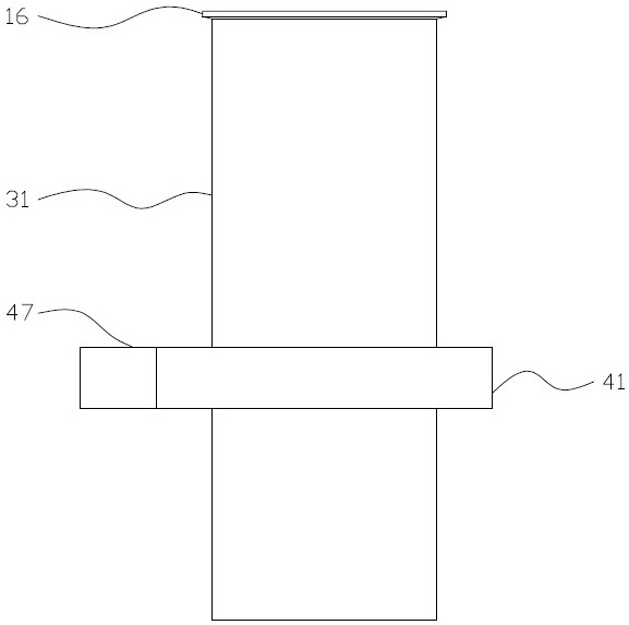
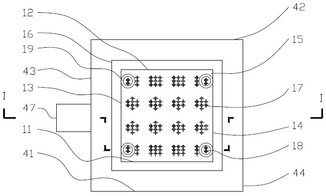
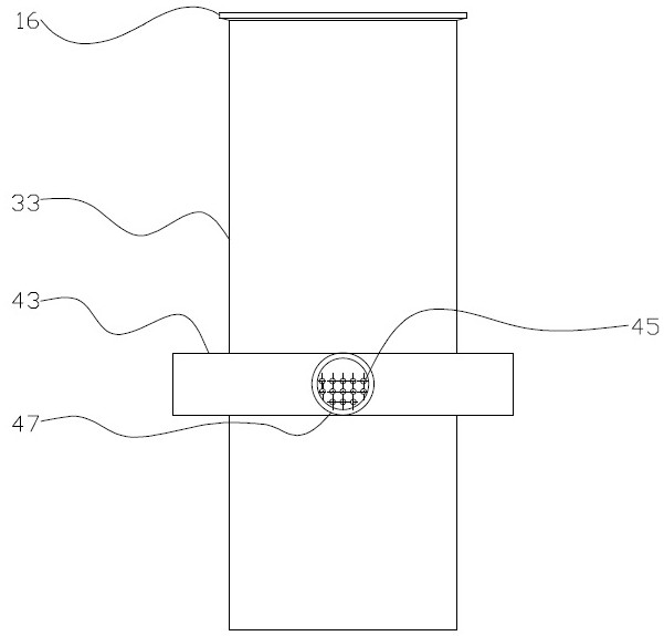
[0030] The following are specific embodiments of the present invention and in conjunction with the attached Figure 1-13 , to further describe the technical solutions of the present invention, but the present invention is not limited to these embodiments.

[0031] A deep denitrification bioretention tank, which can be divided into a planting room 1, a reaction tank 2, a drip filter 3, and a drainage ring pipe 4 from top to bottom; the planting room 1 is a hollow cuboid with an open upper end and a sealed bottom; The reaction tank 2 is a hollow cuboid with an open upper end and a sealed bottom, and is located outside the planting room 1; the dripping filter tube 3 is a vertically placed hollow circular tube with two ends open, the number is 16, and it is located in the planting room. The lower part of the chamber 1; the drainage ring pipe 4 is a hollow square pipe with both ends sealed, which surrounds the outer middle part of the reaction pool 2.

[0032] The planting chamber...


PUM


Abstract

The invention belongs to the technical field of sponge city construction and rainwater treatment, and relates to a bioretention pond device with a deep denitrification function, which is suitable for retention and treatment of urban rainfall with relatively serious pollution and relatively high nitrogen and phosphorus concentration. The device comprises a planting chamber located on the upper portion of the inner side, a trickling filter pipe located on the lower portion of the inner side, a reaction tank located on the outer side and a drainage ring pipe located in the middle of the outer side. A front chamber plate, a rear chamber plate, a left chamber plate, a right chamber plate and a bottom chamber plate form a hollow cavity structure of the planting chamber; ventilation pipes are located at four corners of the planting chamber; the trickling filter pipe is positioned at the lower part of the planting chamber; the reaction tank comprises a front tank wall, a rear tank wall, a left tank wall, a right tank wall and a bottom tank wall; and a front pipe section, a rear pipe section, a left pipe section and a right pipe section form a mouth-shaped annular loop of the drainage ring pipe. The invention provides the bioretention pond device which is simple to operate and maintain and has outstanding rainwater retention capacity and relatively strong nitrification and denitrification capacity.

Description

technical field [0001] The invention belongs to the technical field of sponge city construction and rainwater treatment, and provides a bioretention tank device with deep denitrification function, which is suitable for stagnation and treatment of urban rainfall with relatively serious pollution and relatively high concentration of nitrogen and phosphorus . Background technique [0002] Sponge city has functions such as runoff reduction and collection, rainwater purification and rational utilization, and is a concept of sustainable urban construction actively advocated by my country in the new era. In the construction of sponge city, using the permeable underlayment to infiltrate, collect and store the urban rainfall runoff, and combine the combined effect of plants + microorganisms + soil to purify the rainwater quality is to implement the low-impact development (LID) strategy and alleviate urban floods. It is an important means to solve the problem of environmental polluti...

Claims


Application Information

Patent Timeline
IPC IPC(8): C02F3/32C02F3/28C02F7/00E03F3/04E03B3/02
CPCC02F3/32C02F3/2806C02F7/00E03F3/04E03B3/02C02F2103/001Y02W10/10Y02A20/108
Inventor 刘树元李珍敏骆嘉樊哲钰邢永涛王春凌
Owner TAIZHOU UNIV
Why Eureka
Try Eureka