Bogie based on easy-to-withdraw shaft type gear box and side beam single-point suspension type motor

A gear box and suspension technology, applied in the direction of bogies, transmission devices driven by electric motors, axle boxes, etc., can solve the problem of increasing the risk of damage to the axle boxes, separate removal, and the layout scheme cannot meet the installation position and vibration reduction indicators, etc. question

Pending Publication Date: 2021-09-14
CRRC CHANGCHUN RAILWAY VEHICLES CO LTD
View PDF2 Cites 0 Cited by
  • Summary
  • Abstract
  • Description
  • Claims
  • Application Information

AI Technical Summary

Problems solved by technology

However, the layout position of the motor hanger t and the gear box hanger u of this installation method that relies on the integral beam body g or the well-shaped beam body h and is completely rigidly connected with the motor hanger t and the gear box hanger u And welding manufacturing process not only puts forward higher requirements on the structural strength and symmetry accuracy of the beam body, but also occupies most of the space inside the conventional frame, resulting in the lack of sufficient axle box layout space inside the existing bogie. As a result, the typical primary suspension device can only be arranged at the two ends of the axle, which not only increases the risk of damage to the axle box, but also increases the overall structural size and turning radius of the bogie, which is not conducive to the improvement of its minimum curve passing capacity. And because the lifting lugs of the casing of the traction motor r are non-removable rigid structures, it interferes with the frame and the gearbox structure and blocks each other, so that the traction motor r cannot be removed from the bottom of the car body directly through the maintenance ditch, but must be used on a truck Only by separating the compartment above the frame from the frame can the traction motor r be withdrawn from the frame, which greatly increases the difficulty of motor maintenance and replacement
At the same time, the rigid connection of the motor hanger t and the gearbox hanger u also leads to the lack of sufficient vibration reduction protection system for the traction motor r and the gearbox s, which in turn makes the auxiliary structures such as the anti-snake shock absorber and the anti-rolling torsion bar n Installation becomes an indispensable and necessary supplement
[0008] In addition, different train design speed requirements or different side beam structures will also have a great impact on the layout space and structural form of the primary suspension device and secondary suspension device, as well as the motor and gearbox, often resulting in the old primary suspension. The layout scheme of the suspension device or the secondary suspension device cannot meet the requirements of the installation position and the vibration reduction index, so it is necessary to overthrow the old reference scheme and make a design improvement with a new concept
[0009] like Figure 7 to Figure 9 As shown, the existing large gear s-2 installed inside the shell s-1 of the snap-fit ​​and spliced ​​gearbox is directly press-fitted with the bearing outer ring s-3-2 on the large gear bearing s-3 to form a coaxial fixed connection Interference fit, the gear box installation shaft section d-1 on the axle d is directly press-fitted with the large gear bearing inner ring s-3-1 on the large gear bearing s-3 to form a coaxial fixed interference fit. The coaxial fixed connection form of the interference fit makes the gearbox installation shaft section d-1, the gearbox bearing s-3 and the large gear s-2 become an inseparable whole, and, due to the snap-fit ​​spliced ​​gearbox shell s- 1 has low structural strength, and it cannot be directly used as the focus point of the withdrawal baffle on the wheel shaft withdrawal press. Moreover, the bearing inner ring of the existing large gear bearing s-3 is too narrow, resulting in that even if the wheel shaft withdrawal pressure The on-board unloading baffle is refitted into a multi-jaw chuck and inserted into the gear box through the axle through hole on the axial side wall of the gear box. However, due to the lack of sufficient radial force points, it is still impossible to reliably clamp the large The inner ring s-3-1 of the gear bearing implements the radial withdrawal blocking force, so that the withdrawal of the axle cannot be directly implemented, and then when the subsequent maintenance of the axle d or the large gear s-2 must be buckled and spliced The gearbox shell s-1 is the first to release the original splicing and fastening state, and remove the axle d, the large gear s-2 and the large gear bearing s-3 that are coaxially fixed with it from the frame as a whole. Then transfer to the axle unloading press to complete the unloading and replacement operation
The process of this method is cumbersome, time-consuming and labor-intensive, and it is impossible to remove and replace the axle d independently without removing the large gear s-2 from the snap-fit ​​spliced ​​gearbox casing s-1, and it is also impossible to maintain the buckle. Under the premise that the shell s-1 of the spliced ​​gearbox is in the fastened state, pull out the axle d separately and directly repair the large gear s-2 in the shell s-1 of the gearbox from the hole left after the axle d is removed. and lubrication maintenance

Method used


Image

  • Bogie based on easy-to-withdraw shaft type gear box and side beam single-point suspension type motor
  • Bogie based on easy-to-withdraw shaft type gear box and side beam single-point suspension type motor
  • Bogie based on easy-to-withdraw shaft type gear box and side beam single-point suspension type motor

Examples


Embodiment Construction

[0068] The present invention will be further described in detail below with reference to the accompanying drawings.

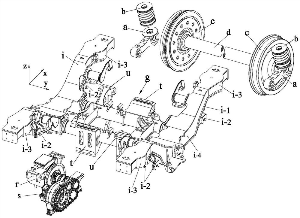
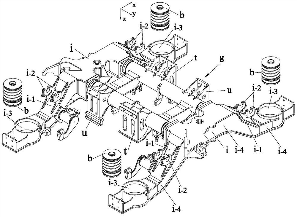
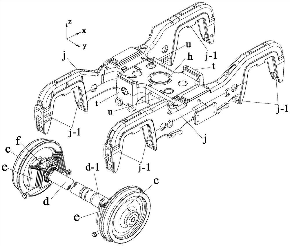
[0069] like Figure 10 to 24 As shown, the steering holder of the present invention based on an easy retractable gearbox and the side beam single-point hanging motor includes a frame A, a wheel pair of wheel C and a axle D, including two frame-side beam A- 1 and two frame beams A-2, frame side beams A-1 include two bird wing connecting portions and in a lower position of the side beams of the side beams and two symmetry stepping in the middle section of the side beam A- 1-1 Bird Wing Side Beam Board Section A-1-2, the bird wing side beam cantilever segment A-1-2 is connected by a horizontal extension section extending outwardly outwardly extended horizontally;

[0070] It is characterized in that the steering holder further includes four annular vibration damper B, easy to retractable gearbox D, side beam single dot hanging motor E and integrated vibration shaker an...


PUM


Abstract

The invention discloses a bogie based on an easy-to-withdraw shaft type gear box and a side beam single-point suspension type motor, and belongs to the field of railway vehicle power bogie devices. The bogie comprises a framework, a wheel set device composed of wheels and axles, four annular vibration reduction shaft boxes, the easy-to-withdraw shaft type gear box, the side beam single-point suspension type motor, an integrated vibration reduction type swing bolster and a secondary suspension system. On the premise that the mounting position and the vibration reduction index of the primary suspension axle box device are ensured, the transverse width size and the turning radius of the whole bogie are effectively reduced, the curve passing capacity of the bogie is further improved, and the annular vibration reduction axle box is convenient to mount, dismount and maintain. After the four fastening bolts are respectively dismounted, the side beam single-point suspension type motor can be directly and independently dismounted from the lower part of the vehicle body through the maintenance trench.

Description

Technical field [0001] The present invention belongs to the field of power bogie for a rail vehicle apparatus, particularly relates to easy-based gearbox shaft back and side frame single point suspended motor bogie. Background technique [0002] Rail train bogie in the design needs to consider not only the structural strength as the main load-bearing frame and yaw dampers and other parts of the damping effect of the subsidiary brake mechanism mounting a combination of factors, the need for different suspension mode demand models, based on the theoretical speed of the train, load bearing, the minimum curvature of the curve and wind snow flying stone, road conditions, integrated design power of the motor bogie, the axle box is placed in position on the axle, the motor and gear box layout space, a series of suspension and two-line structure and layout space and many other factors like suspension means. All kinds of design revolves around these core ideas to improve and increasingly ...

Claims


Application Information

Patent Timeline
IPC IPC(8): B61F5/52B61C9/50B61F15/20B61F5/10B61F5/12B61F5/30B61K9/06
CPCB61F5/52B61C9/50B61F15/20B61F5/10B61F5/12B61F5/305B61K9/06
Inventor 阴晓铭林勤崔冬杰李芬
Owner CRRC CHANGCHUN RAILWAY VEHICLES CO LTD
Why Eureka
Try Eureka