
Textile printing and dyeing wastewater recovery treatment system and method thereof

A waste water recovery and treatment system technology, which is applied in textile industry waste water treatment, multi-stage water treatment, water/sewage treatment, etc., can solve the problems of low use efficiency and poor use effect, and achieve the effect of improving the actual use efficiency

Pending Publication Date: 2021-09-17
翁作容
View PDF9 Cites 1 Cited by
  • Summary
  • Abstract
  • Description
  • Claims
  • Application Information

AI Technical Summary

Problems solved by technology

[0003] However, in the prior art, textile printing and dyeing will use more water resources. At the same time, because the wastewater used in the textile printing and dyeing process contains more dyeing reagents and textile residues, it is impossible to directly discharge the wastewater, and the wastewater needs to be effectively treated. The discharge can only be discharged according to the discharge standard, while the existing textile printing and dyeing wastewater recycling and treatment device can only process a certain amount of wastewater each time, and at the same time, the actual wastewater treatment process needs to be treated step by step and multiple times at intervals, which leads to the recycling of the existing textile printing and dyeing wastewater. The actual use efficiency of the processing device is low, resulting in poor actual use effect of the device

Method used


Image

  • Textile printing and dyeing wastewater recovery treatment system and method thereof
  • Textile printing and dyeing wastewater recovery treatment system and method thereof
  • Textile printing and dyeing wastewater recovery treatment system and method thereof

Examples


Embodiment 1

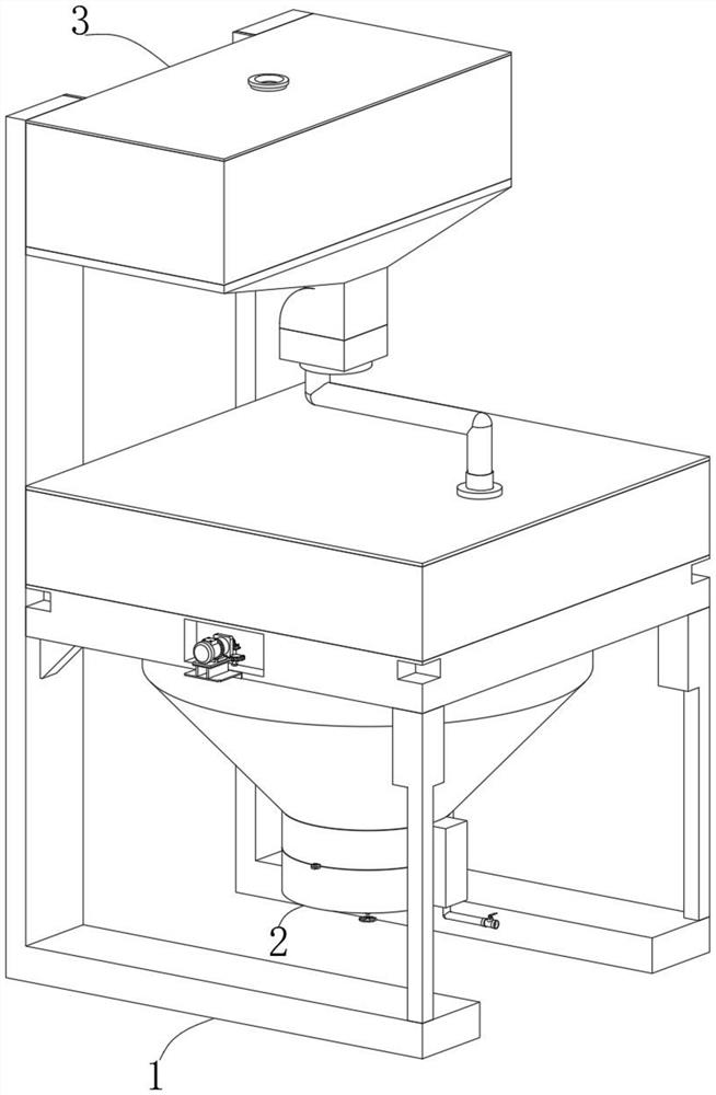
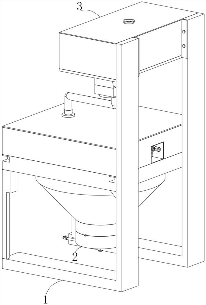
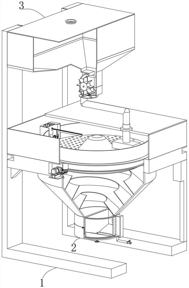
[0037] Embodiment one, with reference to Figure 1-12 : A textile printing and dyeing wastewater recovery treatment system, comprising: a first filter mechanism 1, the first filter mechanism 1 includes two support bases 101, cleaning components and driving components, the establishment of the support base 101 provides an installation basis for other functional components of the equipment The bottom frame 102 is fixedly connected to the top of the two support bases 101. The establishment of the bottom frame 102 facilitates the installation and setting of other functional parts of the equipment. The bottom of the bottom frame 102 is connected with a spiral mixing frame 109. The reagents for degradation can fully react, and the inner surface wall of the bottom frame 102 is equidistantly fixedly connected with a plurality of supporting plates along the circumferential direction. The supporting plates are set up to facilitate the installation and setting of the first supporting shaf...


PUM


Abstract

The invention discloses a textile printing and dyeing wastewater recovery treatment system and a method thereof. The textile printing and dyeing wastewater recovery treatment system comprises a first filtering mechanism, the first filtering mechanism comprises two supporting seats, a cleaning part and a driving part, the tops of the two supporting seats are fixedly connected with a bottom frame, and the bottom of the bottom frame communicates with a spiral mixing frame; and a plurality of supporting pieces are fixedly connected to the inner surface wall of the bottom frame in the circumferential direction at equal intervals. According to the invention, wastewater and a degradation reagent are continuously injected into a liquid storage frame, so that the wastewater can be effectively injected into a mixing frame through the liquid storage frame, and flowing water flow in the process can effectively impact a linkage impeller, so that the linkage impeller can effectively drive a second bevel gear to rotate through a first linkage shaft; and under the cooperation of two second bevel gears, a first linkage shaft can effectively drive a second linkage shaft to rotate, and then the second linkage shaft can effectively drive stirring blades to stir and mix wastewater and degradation reagents.

Description

technical field [0001] The invention belongs to the technical field of waste water recovery equipment, in particular to a textile printing and dyeing waste water recovery treatment system and a method thereof. Background technique [0002] Printing and dyeing, also known as dyeing and finishing, is a processing method and a general term for pretreatment, dyeing, printing, finishing, washing, etc. [0003] However, in the prior art, textile printing and dyeing will use more water resources. At the same time, because the wastewater used in the textile printing and dyeing process contains more dyeing reagents and textile residues, it is impossible to directly discharge the wastewater, and the wastewater needs to be effectively treated. The discharge can only be discharged according to the discharge standard, while the existing textile printing and dyeing wastewater recycling and treatment device can only process a certain amount of wastewater each time, and at the same time, th...

Claims


Application Information

Patent Timeline
Patent Type & Authority Applications(China)
IPC IPC(8): C02F9/04C02F103/30
CPCC02F1/00C02F1/001C02F2301/08C02F2303/16C02F2103/30
Inventor 翁作容
Owner 翁作容
Learn More