
Photocatalytic water treatment device

A water treatment device and photocatalytic technology, applied in the direction of light water/sewage treatment, oxidized water/sewage treatment, water/sewage treatment, etc., can solve the problems of redundant waste gas and sludge, long consumption time of bacteria, large volume, etc. , achieve the effect of reducing COD and VOC, high redox efficiency and increasing reaction area

Active Publication Date: 2021-09-21
青岛科吉环境技术工程有限公司
View PDF5 Cites 0 Cited by
  • Summary
  • Abstract
  • Description
  • Claims
  • Application Information

AI Technical Summary

Problems solved by technology

However, the activated sludge process occupies a large area and has high operating costs; at the same time, the two-stage activated sludge process produces a large amount of sludge, which has poor impact resistance and high environmental requirements.
Once a large number of bacteria die due to environmental reasons, it will directly lead to unqualified water quality, and it will take a long time to re-cultivate and domesticate the bacteria
[0003] The treatment equipment using this sludge method is usually bulky, has high operating costs, and is prone to generate excess waste gas and sludge
However, photocatalytic technology or light-induced technology can avoid these problems well, so a solution that can apply photocatalytic technology to water treatment is needed to solve the unsolvable problems of existing sewage treatment solutions, and at the same time make up for its existing problems. insufficient

Method used


Image

  • Photocatalytic water treatment device
  • Photocatalytic water treatment device
  • Photocatalytic water treatment device

Examples


Embodiment 1

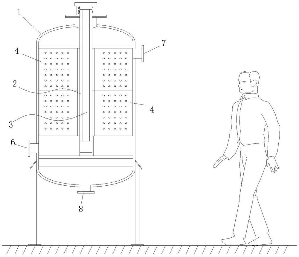
[0028] This embodiment aims to provide a water treatment device using photocatalytic technology. A reaction unit is added to the original tank body 1, and the original simple biological sedimentation tank is improved, so that the process of water treatment overcomes the limitations of the prior art. Defects, Maximize Benefits.

[0029] The method of use in this embodiment is as follows: connect the sewage water supply pipe to the water inlet 6 of the tank body 1, and supply water to the tank body 1 through the water inlet 6; the sewage in the tank body 1 drives the filler 5 to gradually submerge the permeable partition 4; Turn on the ultraviolet lamp 3, and the ultraviolet light causes the titanium dioxide nano-coating on the filler 5 and the water-permeable partition 4 to produce an oxidation-reduction reaction; open the water outlet 7 on the top of the tank body 1, and discharge the treated water with a better cleanliness in the upper layer; when it is necessary to clean Whe...

Embodiment 2

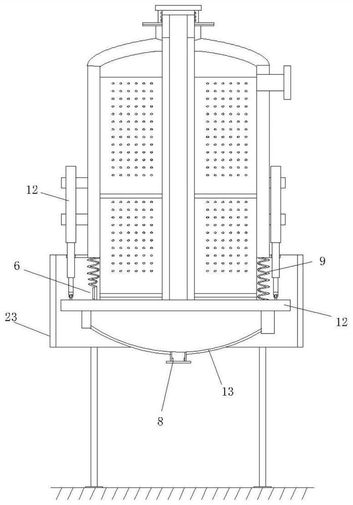
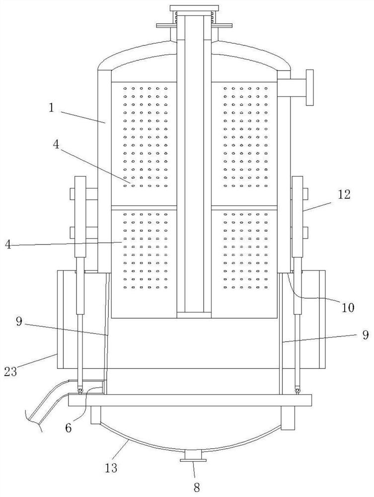
[0035] In the first embodiment, since the space in the tank body 1 is fixed, and most of the sewage contains sludge, the sludge in the tank is getting bigger and bigger, and the space is getting smaller and smaller. This embodiment is made on the basis of the first embodiment, and the purpose is to solve the above-mentioned problems. The measures taken are to add a space expansion mechanism on the basis of the tank body 1 and the reaction unit.

[0036] The operation process of this embodiment is as follows: when the space needs to be expanded, start the lifting device 12 to drive the fixed seat 11 down, and the soft multi-layer composite water-proof cloth 9 is gradually stretched from the contracted state; when the soft multi-layer composite water-proof cloth 9 Fixing seat 11 stops descending when being fully straightened.

[0037] The circulation interval is located between the water inlet 6 and the water-permeable partition 4 , and since the water inlet 6 is set on the wate...

Embodiment 3

[0045] This embodiment is made on the basis of the second embodiment to provide better safety protection for the space expansion mechanism and avoid uncontrolled fall of the space expansion mechanism when the lifting device 12 fails.

[0046] The operating principle of this embodiment is as follows: when the fixed seat 11 descends, it drives the sliding sleeve 21 to move downward, and the limit mechanism located in the fixed sleeve 20 shrinks as the sliding sleeve 21 descends. The reaction force is applied to buffer the decline of the space expansion mechanism.

[0047] The bottom of the tank body 1 is also provided with a telescopic support leg 19, which is composed of a fixed sleeve 20 and a sliding sleeve 21 worn together, the fixed sleeve 20 is fixed on the ground, and the sliding sleeve 21 is fixed on the ground. At the bottom of the ring-shaped fixed seat 11, the telescopic leg 19 is provided with a limiting mechanism, which is used to limit the maximum contraction strok...


PUM


Abstract

The invention relates to a photocatalytic water treatment device comprising a tank body, a reaction unit arranged in the tank body, an ultraviolet lamp, water-permeable partition plates and filler; the reaction unit comprises a transparent lamp tube, the transparent lamp tube is inserted into the tank body from an opening of the tank body, and the transparent lamp tube is subjected to waterproof sealing treatment; the ultraviolet lamp is arranged in the transparent lamp tube; the plurality of water-permeable partition plates are fixed to the inner wall of the tank body and distributed in a circular array mode with the transparent lamp tube as the center, and a plurality of water-permeable holes are formed in the water-permeable partition plates; the filler is arranged in the tank body; a water inlet of the tank body is formed in the bottom of one side, the direction of water flowing into the tank body through the water inlet deviates from the central axis of the tank body, and a water outlet is formed in the top of the opposite side; the bottom of the tank body protrudes outwards in an arc shape, and a sludge outlet is further formed in the bottom; the water-permeable partition plates extend in the length direction of the transparent lamp tube, a circulation interval allowing water to freely circulate is formed between the bottoms of the water-permeable partition plates and the bottom of the tank body, and water from the water inlet is firstly poured into the circulation interval; and titanium dioxide coating layers are coated on the water-permeable partition plates and the filler.

Description

technical field [0001] The invention relates to a water treatment device, in particular to a device using photocatalytic treatment. Background technique [0002] At present, the advanced process treatment of manure in farms mostly uses activated sludge method, or its derivative process. However, the activated sludge process occupies a large area and has high operating costs; at the same time, the two-stage activated sludge process produces a large amount of sludge, has poor impact resistance, and has high environmental requirements. Once a large number of bacterial species die due to environmental reasons, it will directly lead to unqualified water quality, and it will take a long time to re-cultivate and domesticate the bacterial species. [0003] The treatment equipment using this sludge method is usually bulky, has high operating costs, and is prone to generate excess waste gas and sludge. However, photocatalytic technology or light-induced technology can avoid these pr...

Claims


Application Information

Patent Timeline
Patent Type & Authority Applications(China)
IPC IPC(8): C02F1/32C02F1/72C02F1/38C02F1/70
CPCC02F1/325C02F1/725C02F1/70C02F1/38C02F2201/002C02F2201/32
Inventor 党振华王斐朱涛
Owner 青岛科吉环境技术工程有限公司
Learn More