
Ocean cross-cavitation-layer sound signal detection system and method based on optical heterodyne

A detection system, a technology of optical heterodyne, applied in measurement devices, measurement of ultrasonic/sonic/infrasonic waves, instruments, etc., can solve the problems of being easily affected by stray light, unfavorable for the integration of underwater vehicles, and the structure of the detection system is large, etc. Achieve the effect of light weight, simple structure and strong anti-interference ability

Active Publication Date: 2021-09-24
TIANJIN UNIV
View PDF5 Cites 2 Cited by
  • Summary
  • Abstract
  • Description
  • Claims
  • Application Information

AI Technical Summary

Problems solved by technology

For the detection of micro-amplitude waves across the surface of the medium layer, laser diffraction detection is an earlier detection method, which has the advantage of non-contact and is suitable for the detection of low-frequency signals. The detection frequency range is tens to hundreds of Hz, but its detection The system structure is relatively large, which is obviously not conducive to the integration of underwater vehicles; the light flux measurement structure is simple, the detection area is large, and the detection range can reach 400-3000Hz, but the result is easily affected by stray light, and the accuracy is very low; through the interference method The advantages of measurement are obvious. It is a non-contact measurement with high measurement accuracy. It can adopt optical fiber structure, which is relatively compact. Accurately collect echo signals and perform noise reduction, which has broad application prospects

Method used


Image

  • Ocean cross-cavitation-layer sound signal detection system and method based on optical heterodyne
  • Ocean cross-cavitation-layer sound signal detection system and method based on optical heterodyne
  • Ocean cross-cavitation-layer sound signal detection system and method based on optical heterodyne

Examples


Embodiment Construction

[0026] The present invention will be described in further detail below in conjunction with the accompanying drawings and specific embodiments. It should be understood that the specific embodiments described here are only used to explain the present invention, not to limit the present invention.

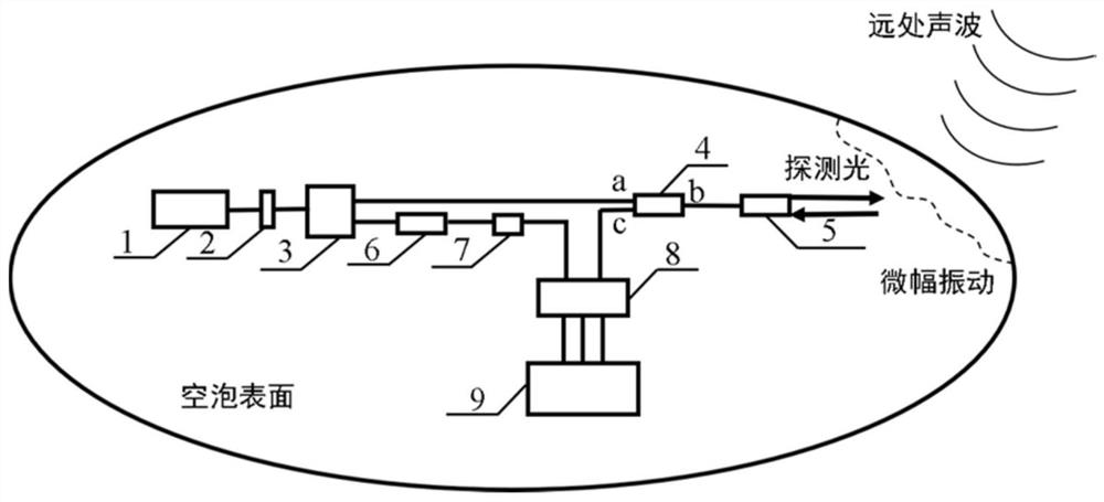
[0027] Such as figure 1 As shown, the present invention provides an ocean transcavitation acoustic signal detection system based on optical heterodyne. The detection process includes a 1550nm single-frequency narrow-linewidth laser 1 passing through an isolator 2 to prevent echoes from interfering with the laser, and then passing through a second A coupler 3 is divided into two optical paths, namely the signal optical path and the reference optical path. The signal optical path is input from the a port of the circulator 4 and then output at the b port. The modulation of the surface micro-amplitude wave caused by the acoustic signal is backscattered to the collimator 5, output from th...


PUM


Abstract

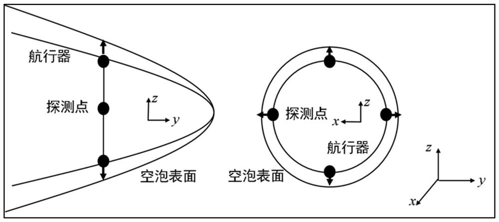
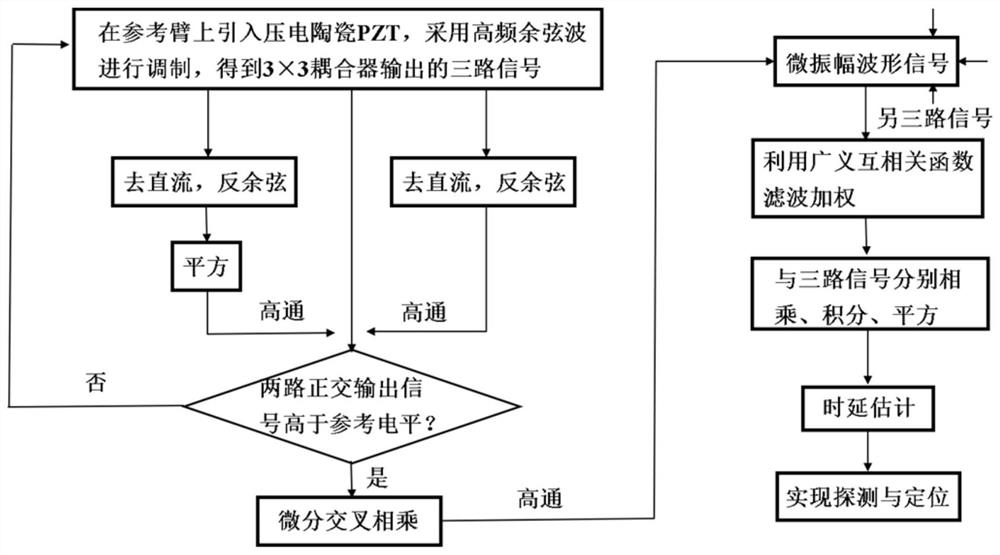
The invention discloses an ocean cross-cavitation-layer sound signal detection system and method based on optical heterodyne, which are used for detecting micro-amplitude vibration on the surface of a cavitation caused by sound pressure transmitted from a remote sound source to a cavitation layer based on an optical heterodyne method so as to realize detection of a remote sound signal. A heterodyne interference signal is obtained by a high-sensitivity photoelectric detection system, a time domain vibration waveform signal generated by superposition of natural low-frequency large-amplitude disturbance on the surface of a cavitation bubble and relative high-frequency micro-amplitude disturbance caused by a sound source is obtained through a demodulation algorithm, and target frequency characteristics are obtained through a signal processing module for inversion; meanwhile, the invention provides a positioning scheme based on quaternary array time delay estimation, according to the scheme, detection system arrangement of a quaternary array is carried out at an aircraft end, time delay estimation is carried out on array detection cavitation bubble surface time domain vibration waveform signals, inversion is carried out on a target distance, azimuth angle information is obtained, and the positioning function based on time delay estimation is achieved.

Description

technical field [0001] The invention belongs to the technical field of underwater acoustic signal detection and identification, and in particular relates to a technique for detecting the micro-amplitude of a cavitation surface of a high-speed aircraft in the ocean by using optical heterodyne interference, so as to realize the detection and positioning of a remote acoustic signal. Background technique [0002] Underwater acoustic signal detection is one of the hot technologies in the marine field. The ocean is an ideal channel for the propagation of acoustic signals. When a bomb of several kilograms explodes in the deep-sea acoustic channel, the signal can still be received 20,000 kilometers away. Information. Therefore, the acoustic signal detection in the ocean channel is simple and easy to implement. However, for some underwater vehicles with high speed, cavitation structure can be generated outside the vehicle to reduce resistance during the voyage. When the distant so...

Claims


Application Information

Patent Timeline
Patent Type & Authority Applications(China)
IPC IPC(8): G01H9/00
CPCG01H9/00Y02A90/30
Inventor 钟凯郑逸哲乔鸿展汪思佳李方杰张献中徐德刚姚建铨
Owner TIANJIN UNIV
Learn More