
Thermal insulation structure at longitudinal diaphragm of low-temperature double-body liquefied gas storage tank and construction method of thermal insulation structure

A liquefied gas storage tank, low-temperature technology, applied in the direction of bulk goods, etc., can solve the problems of insulation damage, insulation failure, evaporation waste, etc., to enhance tensile and crack resistance, improve deformation resistance, compression manufacturing The effect of duration

Pending Publication Date: 2021-09-28
JIANGSU LANYU INSULATION TECH
View PDF0 Cites 0 Cited by
  • Summary
  • Abstract
  • Description
  • Claims
  • Application Information

AI Technical Summary

Problems solved by technology

However, the double-body tank is the joint of two tanks at the mediastinal compartment. Affected by the deformation and low-temperature shrinkage of the tanks on both sides, there are often cases of thermal insulation damage and thermal insulation failure, which lead to transpiration of liquid cargo and waste of vapor discharge. Laws and regulations that trigger the prohibition of evaporative emissions in offshore areas
At the same time, it is also necessary to empty the liquid cargo tank in the later maintenance, and specially arrange a period of time to visit the port to invite professional insulation manufacturers to carry out maintenance and repairs, which increases the cost of money and time.

Method used


Image

  • Thermal insulation structure at longitudinal diaphragm of low-temperature double-body liquefied gas storage tank and construction method of thermal insulation structure

Examples


Embodiment Construction

[0025] The technical solutions in the embodiments of the present invention will be described in detail below in conjunction with the accompanying drawings in the embodiments of the present invention. Obviously, the described embodiments are only some of the embodiments of the present invention, not all of them. Based on the embodiments of the present invention, all other embodiments obtained by persons of ordinary skill in the art without making creative efforts belong to the protection scope of the present invention.

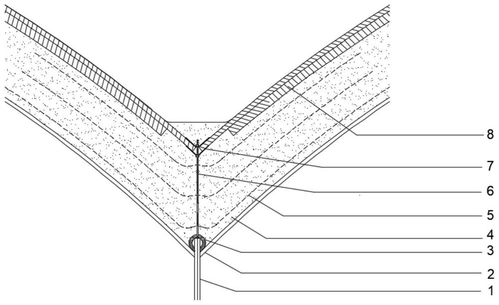
[0026] combine figure 1 As shown, the present invention relates to a thermal insulation structure at the mediastinal cabin of a low-temperature double-body liquefied gas storage tank. Polyurethane insulation construction is started on the mediastinal cabin 1 of the double-body tank and the surface 2 of the nearby double-body tank, and a buffer layer 3 and a reinforcing screw 6 are installed respectively. , and then the insulation layer 4 is installed, and the g...


PUM


Abstract

The invention discloses a thermal insulation structure at a longitudinal diaphragm of a low-temperature double-body liquefied gas storage tank and a construction method of the thermal insulation structure. The structure is arranged on the surface of a longitudinal compartment of the double-body tank and the surface of the adjacent double-body tank, and sequentially comprises a buffer layer, a polyurethane heat preservation layer, a glass fiber crack arrest net layer, a flange plate and a heat preservation outer protection layer from bottom to top. Compared with the prior art, the thermal insulation structure at the longitudinal bulkhead of the low-temperature double-body liquefied gas storage tank and the construction method of the thermal insulation structure at the longitudinal bulkhead at the low-temperature double-body liquefied gas storage tank at least have the following beneficial effects that a reinforced longitudinal bulkhead thermal insulation construction method is provided besides two traditional cryogenic liquid cargo tank thermal insulation construction modes. Therefore, the thermal insulation anti-deformation performance of the longitudinal compartment of the double-body tank can be improved to the maximum extent. The multiple layers of crack arrest nets can greatly enhance the overall tensile and crack resistance of the polyurethane heat preservation plate, and the reinforcing screws and the flange plates can effectively bear the heat preservation weight. Thus, the existing technology does not need to be greatly and fundamentally changed, so that the cost can be saved and the manufacturing period can be shortened to the maximum extent.

Description

technical field [0001] The present application relates, in particular, to a thermal insulation structure at the mediastinal cabin of a low-temperature double-body liquefied gas storage tank and a construction method thereof. Background technique [0002] As an excellent insulation material, polyurethane foam is widely used in building insulation and marine ultra-low temperature liquid cargo tanks. Due to its soft texture and insufficient tensile and crack resistance, polyurethane foam itself is prone to low-temperature shrinkage cracking, penetrating cracks, and insufficient mechanical properties in the case of ultra-low temperature liquid cargo tank insulation. The double-body low-temperature liquid cargo tank can greatly improve the liquid cargo loading rate, and more effectively increase the space utilization rate. The current application scenarios and application penetration rate have greatly increased. However, the double-body tank is the joint of two tanks at the medi...

Claims


Application Information

Patent Timeline
IPC IPC(8): B63B25/16
CPCB63B25/16F17C13/001F17C3/04F17C2201/0152F17C2201/052F17C2203/011F17C2203/0333F17C2203/035F17C2203/0624F17C2209/221F17C2209/228F17C2209/232F17C2260/011
Inventor 陈邦南志伟王家清李星云李翔
Owner JIANGSU LANYU INSULATION TECH
Learn More