Self-heating type rapid hydrogen supply device

A self-heating, rapid technology, applied in the installation device of the container structure, the geometry/arrangement/size of the container structure, gas/liquid distribution and storage, etc., can solve the problem of high water purity and the inability of hydrogen production reactants to circulate Use and other issues to achieve the effect of low material purity requirements, easy reuse, and easy disassembly and assembly

Inactive Publication Date: 2021-10-01
GRIMAT ENG INST CO LTD
View PDF9 Cites 1 Cited by
  • Summary
  • Abstract
  • Description
  • Claims
  • Application Information

AI Technical Summary

Problems solved by technology

Therefore, in scenarios where rapid hydrogen supply is required, additional heating equipment must be carried
[0006] 2. The problem of device portability
This type of method has several limitations: 1. Higher requirements on the purity of water; 2. The interior of the reaction tank needs to be cleaned after each hydrogen production reaction; 3. The hydrogen production reactants cannot be recycled; 4. Contains impurities such as water vapor and oxygen, which need to be removed
The hydrogen production method that CN111244510A adopts is the electrolysis water manufacturing method, and the limitation of existence is also as mentioned above

Method used


Image

  • Self-heating type rapid hydrogen supply device

Examples


Embodiment 1

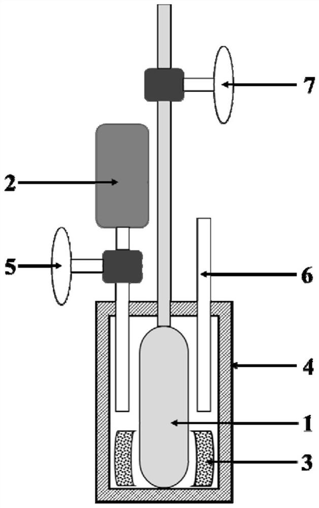
[0052]Such as figure 1 As shown, the self-heating rapid hydrogen supply device provided by the present invention includes a hydrogen storage tank 1 , a water supply tank 2 , a heating pack 3 , an insulation shell 4 , a water tank valve 5 , a thermometer 6 and a hydrogen valve 7 . The hydrogen storage tank 2 is located in the middle of the thermal insulation shell 4, and the heating pack 3 is attached to the hydrogen storage tank 1. The heating pack 3 is filled with quicklime, a heating agent, and the water storage tank 2 is located above the thermal insulation shell 4. The water tank valve 5 controls the opening and closing of water, thereby controlling the inflow of water and preventing the thermal insulation shell from expanding; the thermometer 6 is inserted into the thermal insulation shell 4, next to the heating pack, and the hydrogen storage tank 1 is externally connected to the hydrogen valve 7 to control the opening and closing of hydrogen.

[0053] The specific struct...

Embodiment 2

[0071] The self-heating rapid hydrogen supply device with the same structure as that of Example 1 is adopted, and the specific structure and use process of its components are as follows:

[0072] Specific structure:

[0073] Structure and assembly of hydrogen storage tank

[0074] The hydrogen storage tank has a length of 30cm, an outer diameter of 8cm, and an effective internal volume of about 120mL. It is designed to be filled with 3500g of titanium-based AB2 hydrogen storage alloy powder, which can realize a hydrogen supply of about 700SL. The hydrogen storage tank is equipped with valves and placed in an insulated shell.

[0075] The structure and assembly of the heating pack

[0076] Take 160g of quicklime heating agent and divide it into 4 parts on average, 40g each, put it into 4 non-woven fabric outsourcing bags, and seal them tightly; fill the 4 heating bags at a density of 1 every 90 degrees, and arrange them around the Around the hydrogen storage tank.

[0077] ...


PUM


Abstract

The invention provides a self-heating type rapid hydrogen supply device. The self-heating type rapid hydrogen supply device specifically structurally comprises a hydrogen storage tank, a water storage tank, a heating bag, a heat preservation shell, a water tank valve, a thermometer and a hydrogen valve, wherein the hydrogen storage tank is located in the middle position of the heat preservation shell, the periphery of the tank body of the hydrogen storage tank clings to the heating bag, the water storage tank is arranged above the heat preservation shell, a water tank valve between the water storage tank and the heat preservation shell controls the opening and closing of water, the thermometer is adjacent to the heating bag, and the hydrogen storage tank is externally connected to the hydrogen valve to control opening and closing of hydrogen. The self-heating type rapid hydrogen supply device has the advantages of rapid heating, simple operation, reusability, no environmental pollution and the like.

Description

technical field [0001] The invention relates to the technical field of solid-state hydrogen storage and hydrogen supply, in particular to a self-heating type rapid hydrogen supply device. Background technique [0002] At present, there are mainly three kinds of hydrogen storage methods that have been put into practical use: gaseous hydrogen storage, liquid hydrogen storage, and solid hydrogen storage based on metal hydrogen storage alloys. Compared with other hydrogen storage methods, solid-state hydrogen storage technology has the advantages of high hydrogen storage density, low pressure, good safety, and high purity of hydrogen, which is an important direction for the development of hydrogen storage technology. The shape of a solid-state hydrogen storage device is usually similar to that of a gaseous or liquid hydrogen storage tank. The difference is that a large amount of hydrogen storage material is loaded in the tank of the solid-state hydrogen storage device, and the h...

Claims


Application Information

Patent Timeline
Patent Type & Authority Applications(China)
IPC IPC(8): F17C13/04F17C13/02F17C1/12F17C13/00
CPCF17C13/04F17C13/026F17C1/12F17C13/00F17C2201/0109F17C2201/032F17C2203/0304F17C2205/0323F17C2221/012F17C2223/0138F17C2225/0123F17C2227/0302F17C2227/0386Y02E60/32
Inventor 王琦叶建华李志念武媛方郭秀梅王树茂蒋利军
Owner GRIMAT ENG INST CO LTD
Why Eureka
Try Eureka