System for co-processing household garbage and sludge in cement kiln

A domestic waste and co-processing technology, applied in dehydration/drying/thickened sludge treatment, combustion methods, lighting and heating equipment, etc., can solve the problems of large volume and inability to adapt to domestic land demand, so as to save construction and operation costs , social benefits and environmental benefits

Pending Publication Date: 2021-10-08
SHANGHAI SUS ENVIRONMENT
View PDF10 Cites 0 Cited by
  • Summary
  • Abstract
  • Description
  • Claims
  • Application Information

AI Technical Summary

Problems solved by technology

Due to the high moisture content and large volume of sludge, traditional sludge disposal methods such as landfill and composting can no longer meet the domestic land demand. How to efficiently and economically dispose of sludge is an urgent problem to be solved in our country

Method used


Image

  • System for co-processing household garbage and sludge in cement kiln
  • System for co-processing household garbage and sludge in cement kiln

Examples


Embodiment 1

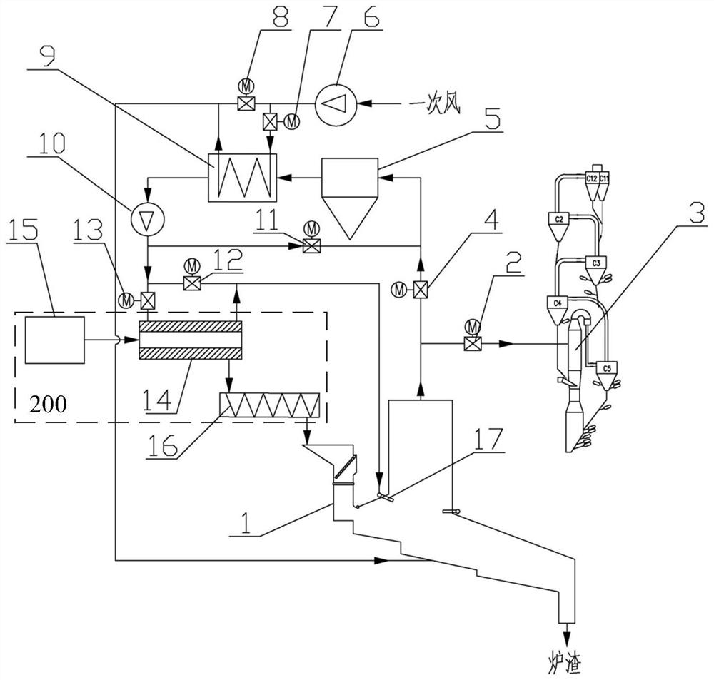
[0077] figure 1 Shown is a schematic diagram of the composition of a better cement kiln co-processing domestic waste and dried sludge system. This system includes the following components.

[0078] Waste incineration unit.

[0079] It is mainly composed of a garbage incinerator 1. The furnace outlet of the garbage incinerator 1 includes a main flue and a furnace flue, and the incinerated slag is used as a cement raw material.

[0080] The garbage incinerator 1 is used for synergistically incinerating dried sludge and domestic garbage. The high-temperature flue gas after the incineration enters the main flue and the exhaust flue through the furnace outlet respectively, and passes through the flue gas respectively arranged on the two flues. The main flue control switch 2 and the furnace flue control switch 4 realize the control of the amount of smoke entering the high-temperature flue. Decomposition unit.

[0081] The decomposition unit is composed of a cement decomposition ...

Embodiment 2

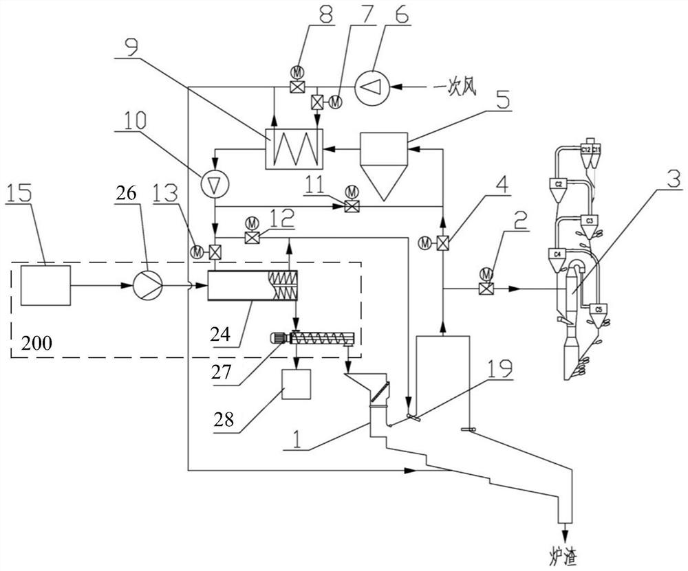
[0107] figure 2 The shown embodiment 2 of this case also includes a waste incineration unit, a decomposition unit, and a flue gas recirculation unit. It is different from embodiment 1 in that the sludge treatment unit 200 uses a sludge low-temperature carbonization unit.

[0108] Specifically, the sludge low-temperature carbonization unit includes a wet sludge storage bin 15, a pressurized pump 26, a sludge carbonization machine 24, and a sludge dehydrator 27, wherein the wet sludge storage bin 15 is connected to the sludge storage bin 15 through a pressurized pump 26. The inlet of the peatization machine 24 and the outlet of the sludge carbonization machine 24 are connected to a sludge dehydrator 27 , and the dehydrated sludge is sent into the garbage incinerator 1 .

[0109] In order to cooperate with the waste water generated after sludge dehydration, this embodiment also adopts a waste water treatment unit 28 .

[0110] Furthermore, the sludge carbonization machine 24 is...


PUM


Abstract

The invention provides a system for co-processing household garbage and sludge in a cement kiln. The system comprises a garbage incineration unit for providing high-temperature flue gas through an output flue of the garbage incineration unit, a sludge treatment unit, a cement decomposition unit connected to the output flue and is used for producing cement under the high-temperature flue gas, and a flue gas recirculation unit arranged between the output flue and the sludge treatment unit; and the flue gas recirculation unit is used for providing the high-temperature flue gas as a heat source for the sludge treatment unit. A process for co-processing the household garbage in the cement kiln is used, sludge is subjected to low-temperature treatment by utilizing waste heat of flue gas, the treated sludge is further conveyed into a garbage incinerator to be incinerated, so that high construction and operation cost is saved, reduction, harmlessness and resourceful treatment on the sludge and the household garbage are realized at the same time, and the system has obvious advantages in economic benefit, social benefit and environmental benefit.

Description

technical field [0001] The invention relates to the technical field of municipal solid waste incineration and sludge disposal, in particular to a cement kiln co-processing domestic solid waste and sludge system. Background technique [0002] The disposal of urban garbage has become a problem of concern all over the world, and it has become a major research topic of environmental protection in today's world. At present, landfill and incineration are the main methods of waste disposal. These two disposal technologies have great disadvantages. The landfill method occupies a large amount of valuable land resources, and the hazard remains for a long time; many domestic waste treatment plants are overloaded, and it is becoming more and more difficult to select a new landfill site. The crisis is likely to spread to more cities. Incineration for power generation will produce fly ash and dioxin and other toxic and harmful gases, causing secondary pollution. In particular, the emis...

Claims


Application Information

Patent Timeline
IPC IPC(8): F23G5/44F23G5/46F23G5/50F23G7/00C02F11/13
CPCF23G7/001F23G5/44F23G5/46F23G5/50F23G5/442C02F11/13
Inventor 龙吉生乔旭瞿兆舟张利军李建平黄立成倪鲲鹏严浩文张坡袁旗斌
Owner SHANGHAI SUS ENVIRONMENT
Why Eureka
Try Eureka