Shaft flow monitoring system and flow and water content interpretation method

A flow monitoring and wellbore technology, used in surveying, earthmoving, wellbore/well components, etc., can solve problems such as stall, measurement accuracy and measurement stability impact, blowout, etc., to achieve easy layout, save mining costs, Accurate effect of air content

Active Publication Date: 2021-10-22
CHINA UNIV OF PETROLEUM (EAST CHINA) +1
View PDF10 Cites 2 Cited by
  • Summary
  • Abstract
  • Description
  • Claims
  • Application Information

AI Technical Summary

Problems solved by technology

[0002] At present, most oilfields in China mainly use turbine flowmeters and related flowmeters to measure the flow rate of horizontal wells. For some horizontal wells with severe sand content and low fluid production, turbine flowmeters are prone to sand stuck, lost rotation, etc. The phenomenon of even stalling will affect the measurement accuracy and measurement stability. Chinese patent document CN104089664B discloses a thermal pulse time-difference type oil-water two-phase flow measurement sensor, which can be used for dynamic monitoring of fluid production profile flow in low fluid production horizontal wells
However, the fluid state during oil pumping is not only water-oil two-phase. When the wellbore is subjected to gas invasion, the gas content will affect the measurement of water cut, resulting in the possibility of multiple solutions for water cut and fluid flow measurement. If gas is contained, the monitoring will not be effective. In time, there is also the risk of a blowout

Method used


Image

  • Shaft flow monitoring system and flow and water content interpretation method
  • Shaft flow monitoring system and flow and water content interpretation method
  • Shaft flow monitoring system and flow and water content interpretation method

Examples


Embodiment 1

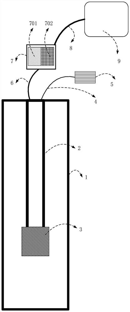
[0063] like figure 1 As shown, a wellbore flow monitoring system, the monitoring system includes a multifunctional carbon fiber optical fiber composite rod 2, an oil well pump 3, a ground pulse heating control system 5, a ground optical fiber monitoring signal acquisition system 7, and computer analysis for optical fiber monitoring data processing and interpretation system9.

[0064] The oil pump 3 is connected to the bottom end of the multifunctional carbon fiber optical fiber composite rod 2 and lowered into the wellbore 1, and the ground pulse heating control system 5 is connected to the top end of the multifunctional carbon fiber optical fiber composite rod 2 through the ground heating control integrated cable 4.

[0065] The ground optical fiber monitoring signal acquisition system 7 is connected to the top of the multifunctional carbon fiber optical fiber composite rod 2 through the ground optical cable 6, and the optical fiber monitoring data processing and interpretati...

Embodiment 2

[0084] like Figure 4 As shown, a method for interpreting the flow rate and water cut rate of oil-water-gas three-phase fluid in an oil well is carried out using the wellbore flow monitoring system described in Example 1. The specific steps are as follows:

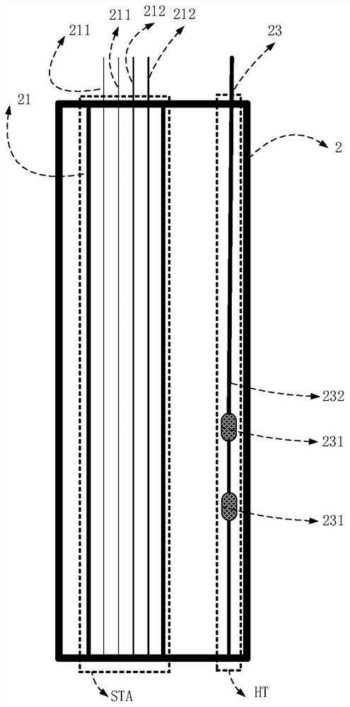
[0085] 1) Start the oil well pump 3 to carry out the liquid drainage work, and collect the background temperature information and sound wave information generated when the fluid in the wellbore 1 flows stably through the multifunctional carbon fiber optical fiber composite rod 2 in real time. The background temperature information refers to that measured before heating The temperature curve formed by the wellbore fluid temperature changing with the well depth;

[0086] 2) Perform interval pulse heating on the fluid at point Y of the wellbore. The point Y corresponds to the location of the HT thermal excitation unit, so that the temperature of the fluid downstream of point Y shows a pulse change, and record the heating powe...

Embodiment 3

[0104] This embodiment is a monitoring data interpretation method for the fluid flow rate and water content of a self-spraying well. The difference from Embodiment 1 is that there is no oil well pump 3 at the lower end of the multifunctional carbon fiber optical fiber composite rod 2 .


PUM


Abstract

The invention belongs to the technical field of oil and gas exploitation, and particularly relates to a shaft flow monitoring system and a flow and water content interpretation method. According to the shaft flow monitoring system, distributed optical fiber temperature monitoring, distributed optical fiber sound wave monitoring and single-point thermal excitation functions are integrated, simultaneous monitoring of multiple parameters of underground temperature and sound waves is achieved, and the requirement for real-time monitoring of the underground fluid state in the high-temperature, high-pressure and corrosive environment is met. The invention further discloses a flow and water content interpretation method. Particularly for oil-water-gas three-phase fluid of an oil well, multi-parameter fusion interpretation is carried out on temperature information and sound wave information after fluid pulse heating, the flow and water content conditions are interpreted from multiple angles, the purposes of mutual verification and multiplicity reduction are achieved, the obtained fluid flow, the water content and the gas content are more accurate, more accurate data support is provided for actual production, the exploitation cost is saved, and the exploitation risk is reduced.

Description

technical field [0001] The invention belongs to the technical field of oil and gas exploitation, and in particular relates to a wellbore flow monitoring system and a flow and water cut interpretation method. Background technique [0002] At present, most oilfields in China mainly use turbine flowmeters and related flowmeters to measure the flow rate of horizontal wells. For some horizontal wells with severe sand content and low fluid production, turbine flowmeters are prone to sand stuck, lost rotation, etc. The phenomenon of even stalling will affect the measurement accuracy and measurement stability. Chinese patent document CN104089664B discloses a thermal pulse time-difference type oil-water two-phase flow measurement sensor, which can be used for dynamic monitoring of fluid production profile flow in low fluid production horizontal wells. However, the fluid state during oil pumping is not only water-oil two-phase. When the wellbore is subjected to gas invasion, the gas c...

Claims


Application Information

Patent Timeline
Patent Type & Authority Applications(China)
IPC IPC(8): E21B47/00E21B47/07E21B49/08
CPCE21B47/00E21B47/07E21B49/08Y02E10/10
Inventor 刘均荣李庆庆吕广平张锦杰
Owner CHINA UNIV OF PETROLEUM (EAST CHINA)
Why Eureka
Try Eureka