Optical blanking structure for refrigeration type infrared detector

An infrared detector and refrigeration type technology, which is applied to the surface coating liquid device, pretreatment surface, coating and other directions, can solve the influence of film forming quality, affect the uniformity of film forming thickness, and the uniformity of coating layer thickness is easy There are problems such as deviation, to achieve the effect of improving smoothness and gloss, avoiding unstable curing of the surface layer, and ensuring the uniformity of the coating

Inactive Publication Date: 2021-10-26
浙江焜腾红外科技有限公司
View PDF7 Cites 2 Cited by
  • Summary
  • Abstract
  • Description
  • Claims
  • Application Information

AI Technical Summary

Problems solved by technology

[0003] In the coating process of the traditional optical blanking structure, the coating roller is generally used to coat the surface coating of the substrate. In the actual use process, the thickness uniformity of the coating layer is prone to deviation due to the coating roller coating method. It affects the uniformity of film thickness in the later stage, and its smoothness and gloss are average, which will affect the film quality of the substrate surface in the later stage, and the traditional substrate will enter the interior of the UV curing machine for curing after the coating is applied. The surface coating of the material is not stable enough in the process of conveying and moving, and it is prone to offset. Direct UV curing will lead to the disadvantage of unstable surface curing, which will affect the film thickness and film quality of the blanking structure. For this reason, we propose An Optical Blanking Structure for Cooling Infrared Detector

Method used


Image

  • Optical blanking structure for refrigeration type infrared detector
  • Optical blanking structure for refrigeration type infrared detector
  • Optical blanking structure for refrigeration type infrared detector

Examples


Embodiment 1

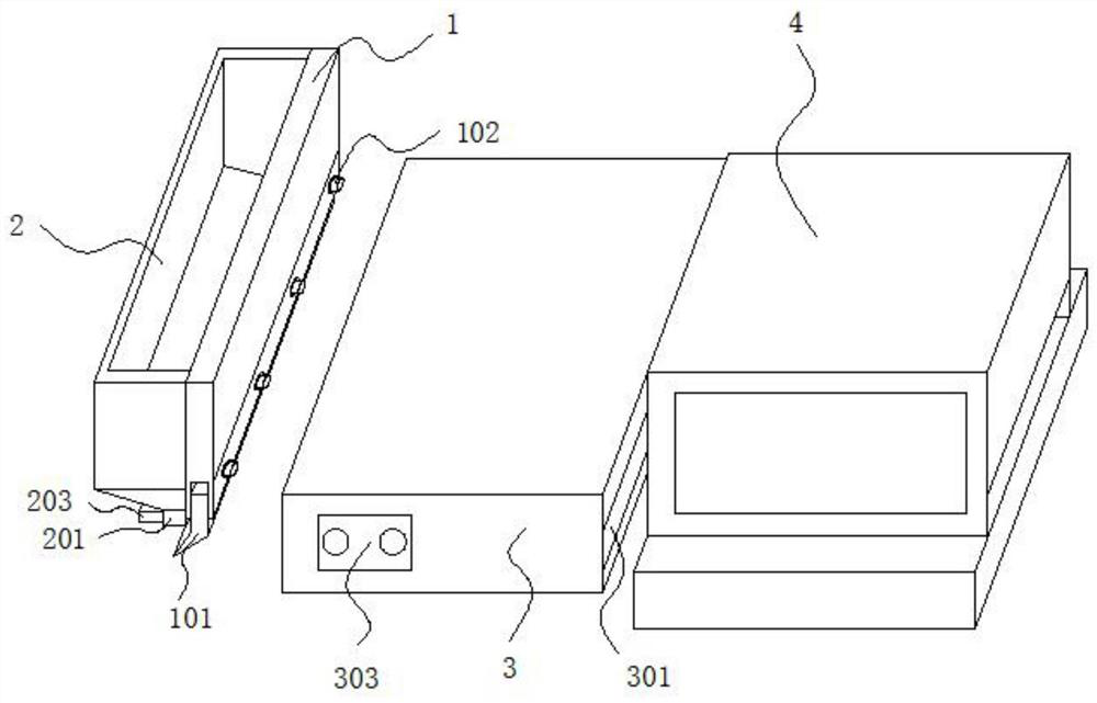
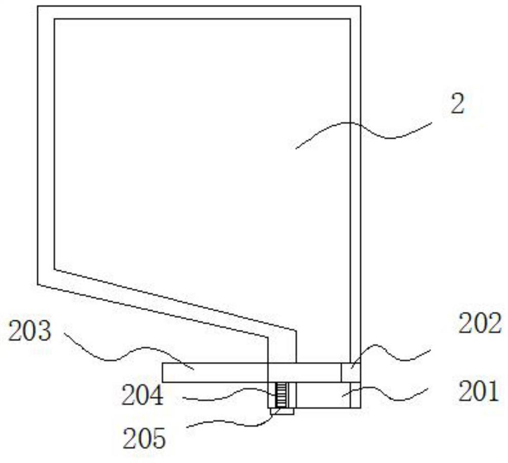
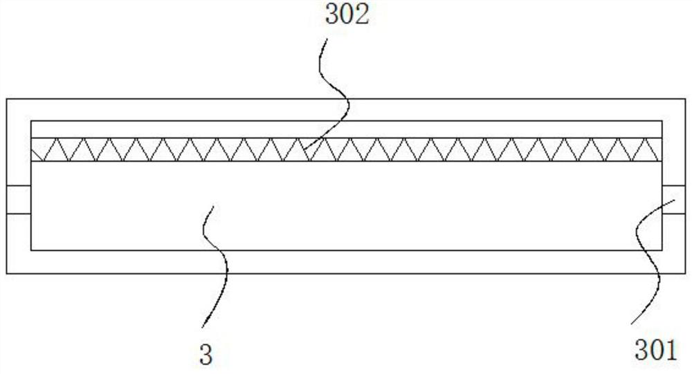
[0021] An optical blanking structure for cooling infrared detectors, comprising a mounting frame and a UV curing machine, a scraper is detachably connected to the bottom of the mounting frame, a storage box is fixedly connected to one side of the surface of the mounting frame, and the The bottom of the material storage box is fixedly connected with a discharge pipe, and a chute is provided in the horizontal direction inside the discharge pipe, and a baffle is inserted inside the chute, and a threaded hole is provided at the bottom of the discharge pipe, and the threaded hole Bolts are screwed inside, and the top of the bolts touches the bottom of the baffle. A pretreatment box is installed between the installation frame and the UV curing machine. Through holes are opened on both sides of the pretreatment box. The pretreatment A heating wire is installed at the bottom inside the box.

[0022] Preferably, an adjusting screw is detachably connected to the bottom of the mounting f...


PUM


Abstract

The invention discloses an optical blanking structure for a refrigeration type infrared detector. The optical blanking structure comprises a mounting frame and a UV curing machine, wherein a scraper is detachably connected to the bottom of the mounting frame, a storage box is fixedly connected to one side of the surface of the mounting frame, a discharging pipe is fixedly connected to the bottom of the storage box, and a chute is formed in the interior of the discharging pipe in a horizontal direction. By using the optical blanking structure disclosed by the invention, a coating is added in a direct discharging mode of the storage box, and the scraper is adopted for scraping; and compared with a traditional coating mode of a coating roller, a coating thickness and the coating uniformity on the surface of a base material can be better guaranteed, the smoothness and the glossiness of the coating are improved, and then the subsequent film forming quality is improved. The surface of a coating layer is pretreated through a high temperature generated by an electric heating wire, so that the surface of the coating layer is dried firstly, the situation that the surface coating deviates in the conveying and moving process of the base material is avoided, the disadvantage that curing o fa surface layer is unstable due to direct UV light curing is overcome at the same time, and a film forming thickness and the film forming quality of the blanking structure are further improved.

Description

technical field [0001] The invention relates to the technical field of optical processing, in particular to an optical blanking structure for cooling infrared detectors. Background technique [0002] The infrared detector is a device that converts the incident infrared radiation signal into an electrical signal output. Infrared radiation is an electromagnetic wave with a wavelength between visible light and microwave, which cannot be detected by the human eye. It is necessary to detect the existence of this radiation and measure its strength , it must be converted into other physical quantities that can be detected and measured. Generally speaking, any effect caused by infrared radiation irradiating objects, as long as the effect can be measured and is sensitive enough, can be used to measure the intensity of infrared radiation. Modern infrared detectors The infrared thermal effect and the photoelectric effect are mainly used. The output of these effects is mostly electricit...

Claims


Application Information

Patent Timeline
Patent Type & Authority Applications(China)
IPC IPC(8): B05C9/12B05C9/14B05C11/04B05C13/02B05D3/02B05D3/06B05C5/02
CPCB05C9/12B05C9/14B05C11/04B05C13/02B05D3/0254B05D3/067B05C5/0245
Inventor 詹健龙王林峰王海成
Owner 浙江焜腾红外科技有限公司
Why Eureka
Try Eureka