
Laser cutting platen structure

A cutting table and board structure technology, applied in instruments, laser welding equipment, optics, etc., can solve the problems of increasing maintenance costs, prolonging Q-time, etc., and achieve the effects of improving cutting efficiency, reducing cost output, and reducing the number of laser cutting times

Active Publication Date: 2021-10-29
FUJIAN HUAJIACAI CO LTD
View PDF9 Cites 0 Cited by
  • Summary
  • Abstract
  • Description
  • Claims
  • Application Information

AI Technical Summary

Problems solved by technology

[0004] In the process of laser cutting, the laser is required to gather the laser into high power, and the high-energy light waves are concentrated on the workpiece. With the extension of the use time of the laser, the energy of the laser gathered by the laser attenuates. It is necessary to increase the number of cutting times to separate the workpiece and prolong the preparation process. Q-time, regular replacement of lasers increases maintenance costs; and with the improvement of workpiece cutting process requirements, high-standard lasers are often required to gather and produce high-energy output lasers

Method used


Image

  • Laser cutting platen structure

Examples


Embodiment Construction

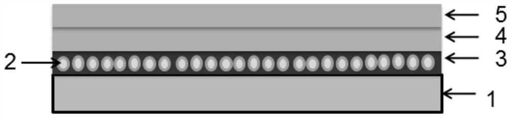
[0017] Such as figure 1 As shown, a laser cutting platen structure of the present invention includes a platen 1, the upper surface of the platen 1 is provided with an organic carrier film 3, and particles 2 with water absorption and scattering effects are dispersed inside the organic carrier film 3; the organic carrier film 3 A first total reflection film 4 and a second total reflection film 5 are sequentially provided on the upper surface of the upper surface from bottom to top, and the first total reflection film 4 and the second total reflection film 5 form a laminated total reflection film structure.

[0018] A layer of organic carrier film 3 is coated on the top of the platen by IJP (inkjet printing) / Coater (coater), and the organic carrier film 3 contains particles 2, wherein the composition of the organic carrier film is not limited to polyimide ( PI), ethylene terephthalate (PET) or polybutylene terephthalate (PBT), preferably polyimide (PI), with a thickness ranging f...


PUM

PropertyMeasurementUnit
Thicknessaaaaaaaaaa
Particle sizeaaaaaaaaaa

Abstract

The invention discloses a laser cutting platen structure which comprises a platen. An organic carrier film is arranged on the upper surface of the platen, and particles with water absorption and scattering effects are dispersed in the organic carrier film; and a first total reflection film and a second total reflection film are sequentially arranged on the upper surface of the organic carrier film from bottom to top, and the first total reflection film and the second total reflection film form a laminated total reflection film structure. According to the cutting platen structure, laser transmitted to the platen from a workpiece can be reflected to the cutting position of the back face of the workpiece, the back face of the cutting position of the workpiece is melted through the reflected energy laser, and cracks are formed; and by means of the laser cutting platen structure, the cutting efficiency is improved, the laser cutting frequency is reduced, laser energy is fully utilized, the service life of a laser device is prolonged, and the cost output is reduced.

Description

technical field [0001] The invention relates to the field of laser cutting machines, in particular to a laser cutting table structure. Background technique [0002] The production process of organic light emitting diode (English full name is Organic Light Emitting Diode, abbreviated as OELD) display panel includes the process of cutting and edging. Laser cutting machine is used to cut the internal lines of OLED panel, and in the small size panel production process In the process, it is necessary to cut large-size glass into small units for the continuation of the subsequent process. The circuit board manufacturing process is complex and fine, so the laser is used to cut the panel, the cutting precision is high, and the impact of cutting and burning is small, which is conducive to improving the product quality. Yield [0003] Laser cutting machine, also known as laser cutting machine, focuses the laser light emitted from the laser device into a high-power-density laser beam ...

Claims


Application Information

Patent Timeline
IPC IPC(8): B23K26/70B23K26/38B23K26/00G02B5/08
CPCB23K26/702B23K26/009B23K26/38G02B5/0833
Inventor 温质康庄丹丹乔小平苏智昱
Owner FUJIAN HUAJIACAI CO LTD
Features
  • Generate Ideas
  • Intellectual Property
  • Life Sciences
  • Materials
  • Tech Scout
  • Unparalleled Data Quality
  • Higher Quality Content
  • 60% Fewer Hallucinations
Learn More