
Waste heat recycling system of complete set of waste oil treatment equipment

A waste heat recovery and complete treatment technology, applied in lighting and heating equipment, heat exchangers, indirect heat exchangers, etc., can solve the problems of excessive exhaust gas temperature, high energy consumption of waste oil, and slow heating of waste oil. Achieve the effect of improving high temperature emission, scientific and reasonable structure, and saving electric energy

Pending Publication Date: 2021-10-29
CHONGQING FANGSHENG CLEANING EQUIP CO LTD
View PDF0 Cites 0 Cited by
  • Summary
  • Abstract
  • Description
  • Claims
  • Application Information

AI Technical Summary

Problems solved by technology

At the same time, in the regeneration of waste oil, the waste heat of the flue gas from the exhaust gas burner is not utilized, and the discharge temperature of the flue gas greatly exceeds the standard
Waste heat is not utilized, resulting in high energy consumption and high production costs for waste oil regeneration
On December 15, 2017, the company applied for a patent titled "A waste heat utilization device for waste oil regeneration rectification catalytic system", the patent number is 2017217512881. This device separates the top line oil and gas from the fractionation tower Partial recovery of the waste heat is used to heat the waste oil, and the top-line oil gas is continuously cooled by water to form liquid oil. The amount of waste oil heated by this device is small, the temperature of the waste oil is also low, and the speed of heating the waste oil is also fast. Slow and insufficient utilization of waste heat

Method used


Image

  • Waste heat recycling system of complete set of waste oil treatment equipment

Examples


Embodiment 1

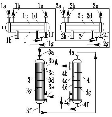
[0014] refer to figure 1 , a waste heat recovery and utilization system for a complete set of waste oil treatment equipment. The system consists of a bottom line oil heat exchanger 1, a side line oil heat exchanger 2, a flue gas rear heat exchanger 3, and a flue gas front heat exchanger 4. Waste oil The four-stage heating, the bottom line oil heat exchanger 1 is the first stage heating, the heating medium is the bottom line oil of the fractionation tower, the side line oil heat exchanger 2 is the second stage heating, the heating medium is the side line oil of the fractionation tower, and the flue gas is exchanged in the rear section Heater 3 is three-stage heating, and the heating medium is flue gas at the rear section of the exhaust gas burner, and the heat exchanger 4 at the front section of flue gas is four-stage heating, and the heating medium is flue gas at the front section of the exhaust gas burner; the bottom line oil heat exchange The device 1 and the side line oil h...

Embodiment 2

[0016] refer to figure 1, a waste heat recovery and utilization system for a complete set of waste oil treatment equipment. The system consists of a bottom line oil heat exchanger 1, a side line oil heat exchanger 2, a flue gas rear heat exchanger 3, and a flue gas front heat exchanger 4. Waste oil The four-stage heating, the bottom line oil heat exchanger 1 is the first stage heating, the heating medium is the bottom line oil of the fractionation tower, the side line oil heat exchanger 2 is the second stage heating, the heating medium is the side line oil of the fractionation tower, and the flue gas is exchanged in the rear section Heater 3 is three-stage heating, and the heating medium is flue gas at the rear section of the exhaust gas burner, and the heat exchanger 4 at the front section of flue gas is four-stage heating, and the heating medium is flue gas at the front section of the exhaust gas burner; the bottom line oil heat exchange The device 1 and the side line oil he...

Embodiment 3

[0018] refer to figure 1 , a waste heat recovery and utilization system for a complete set of waste oil treatment equipment. The system consists of a bottom line oil heat exchanger 1, a side line oil heat exchanger 2, a flue gas rear heat exchanger 3, and a flue gas front heat exchanger 4. Waste oil The four-stage heating, the bottom line oil heat exchanger 1 is the first stage heating, the heating medium is the bottom line oil of the fractionation tower, the side line oil heat exchanger 2 is the second stage heating, the heating medium is the side line oil of the fractionation tower, and the flue gas is exchanged in the rear section Heater 3 is three-stage heating, and the heating medium is flue gas at the rear section of the exhaust gas burner, and the heat exchanger 4 at the front section of flue gas is four-stage heating, and the heating medium is flue gas at the front section of the exhaust gas burner; the bottom line oil heat exchange The device 1 and the side line oil h...


PUM

PropertyMeasurementUnit
Diameteraaaaaaaaaa
Wall thicknessaaaaaaaaaa
Lengthaaaaaaaaaa

Abstract

The invention discloses a waste heat recycling system of a complete set of waste oil treatment equipment, and relates to a heating device for waste oil regeneration. The system is characterized in that a bottom line oil heat exchanger, a side line oil heat exchanger, a flue gas rear-section heat exchanger and a flue gas front-section heat exchanger form four-stage heating of waste oil; a heating medium of the bottom line oil heat exchanger is bottom line oil of a fractionating tower, a heating medium of the side line oil heat exchanger is side line oil of the fractionating tower, a heating medium of the flue gas rear-section heat exchanger is flue gas of the rear section of a waste gas burner, and a heating medium of the flue gas front-section heat exchanger is flue gas of the front section of the waste gas burner; the bottom line oil heat exchanger and the side line oil heat exchanger are horizontal cylindrical tank bodies with the same structure, and the flue gas rear-section heat exchanger and the flue gas front-section heat exchanger are vertical hanging type tank bodies with the same structure; and four stages of waste oil heaters are connected in series through pipelines and pipe fittings. The system is scientific and reasonable in structure, safe and reliable, saves energy, reduces the cost of waste oil regeneration, greatly improves high-temperature emission of flue gas, facilitates emission and has popularization value.

Description

technical field [0001] The invention relates to a heating device for waste oil regeneration, and more specifically to a waste heat recovery and utilization system of waste oil complete processing equipment. Background technique [0002] In the regeneration of waste oil, especially in the complete set of waste oil treatment equipment, a large amount of electricity is required to heat the waste oil, and the heating temperature of the waste oil needs to be determined according to the type of waste oil regeneration and the regeneration process. In the process of rectifying and catalytically regenerating waste oil, it is necessary to heat the waste oil to 200°C-400°C to vaporize the waste oil and separate the bottom line oil, side line oil and top line oil gas. In waste oil regeneration, the bottom line oil, side line oil, and top line oil gas separated by the fractionation tower need to be cooled. In the past, the bottom line oil and side line oil were all cooled naturally, and ...

Claims


Application Information

Patent Timeline
IPC IPC(8): F28D7/16F28D21/00F23J15/06
CPCF28D7/1607F28D21/0001F23J15/06Y02E20/30
Inventor 豆远奎
Owner CHONGQING FANGSHENG CLEANING EQUIP CO LTD
Learn More