Air-cooled galvanic pile environment simulation test system and control method thereof

An environmental simulation and testing system technology, applied in circuits, measuring devices, fuel cells, etc., can solve the problems of increasing the number of space ventilation, energy consumption of large vacuum ventilation, and increasing ventilation emissions, so as to reduce ventilation energy. The effect of reducing power consumption, reducing volume and facilitating stable operation

Pending Publication Date: 2021-10-29
大连锐格新能源科技有限公司
View PDF3 Cites 3 Cited by
  • Summary
  • Abstract
  • Description
  • Claims
  • Application Information

AI Technical Summary

Problems solved by technology

Since the hydrogen tail gas of this technology is exhausted in the environmental chamber, in order to control the hydrogen concentration and reduce the impact of hydrogen emitted by the cathode, it is necessary to increase the ventilation discharge or increase the space to dilute the hydrogen, resulting in an increase in space or an increase in the number of space ventilation. In the commonly used simulated high-altitude low-pressure operation, this technology needs to spend a lot of energy for vacuum ventilation

Method used


Image

  • Air-cooled galvanic pile environment simulation test system and control method thereof
  • Air-cooled galvanic pile environment simulation test system and control method thereof
  • Air-cooled galvanic pile environment simulation test system and control method thereof

Examples


Embodiment 1

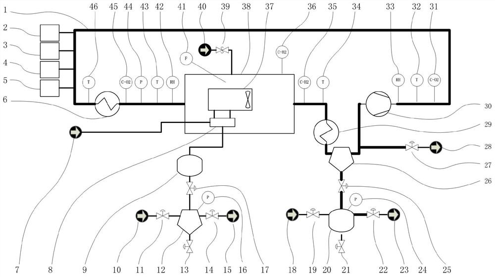
[0042] exist figure 1 Among them, the environmental simulation test device of the air-cooled stack consists of the main body of the test device equipped with the stack to be tested, that is, the environmental chamber 38 where the air-cooled stack 37 to be tested is placed, the hydrogen management system connected to the environmental chamber 38 and the external air management system. system composition.

[0043] The ambient simulated air in the external air duct system enters and exits from the opposite side of the environmental chamber 38. For the convenience of expression, the air enters from the left side and flows out from the right side in this figure, which is a non-limiting relative orientation. The air-cooled electric stack 37 to be tested is placed in the middle of the environmental chamber 38. The air-cooled electric stack 37 has the same fan induction direction as the aforementioned left-in and right-out. There is a gap between the air-cooled electric stack 37 and t...

Embodiment 2

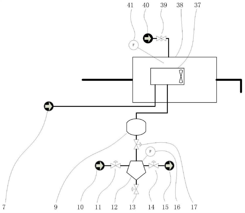
[0048] Such as figure 2 As shown, different from Example 1, the tested air-cooled stack 37 in this example has its own hydrogen management system to control the discharge of hydrogen by itself, and the environmental simulation test device of the air-cooled stack 37 only provides the hydrogen source 7, but does not provide The electric stack has its own hydrogen controller 8, and the hydrogen discharge generated by the air-cooled electric stack 37 directly enters the tail gas buffer 9, and the rest are the same as in the first embodiment.

Embodiment 3

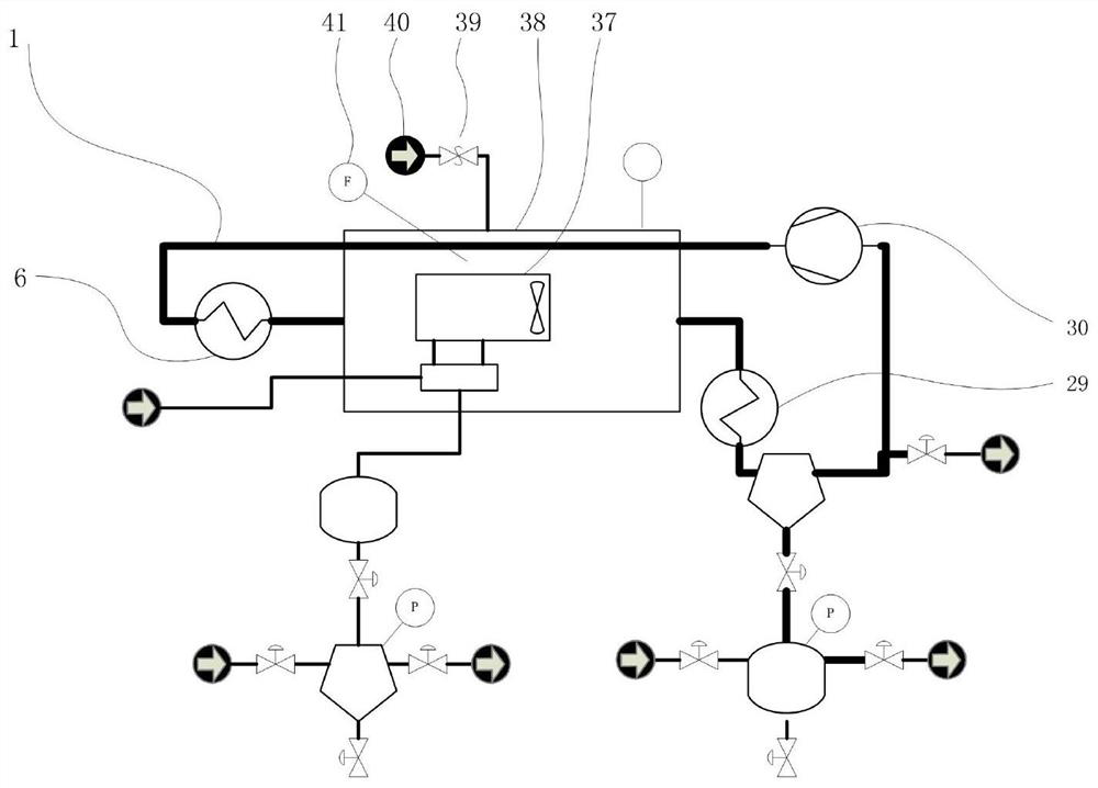
[0050] Such as image 3 As shown, the circulation pipeline 1 passes through the interior of the environment chamber 38 after passing through the circulation fan 30 , and then enters into the interior of the environment chamber 38 through the temperature raising heat exchanger 6 . This layout reduces the overall external dimensions compared to that of Embodiment 1. Other hydrogen exhaust gas management systems, various sensors, and other parts of the air management system that do not pass through the environmental chamber 38, and their relative positions and functions remain unchanged.


PUM


Abstract

The invention discloses an air-cooled stack environment simulation test system and a control method thereof, and relates to an environment simulation device structure and an operation control method for fuel cell air-cooled stack test. More specifically, the invention relates to a test device condition and operation management method capable of simulating ambient air pressure, especially low air pressure, and controlling temperature, humidity, oxygen concentration and hydrogen concentration. Simulation conditions closer to actual operation can be obtained, test energy consumption can be reduced, and stable operation of the test is facilitated. Under the condition that the pressure of the hydrogen exhaust port is kept to be the same as the set environment pressure, hydrogen tail gas is not discharged into circulating air of the testing device, the ventilation energy consumption can be greatly reduced, especially the energy consumption of vacuum pumping under the pressure reduction condition, and the system safety is improved.

Description

technical field [0001] The present invention relates to the structure and control method of an environment simulation device for fuel cell air-cooled stack testing, more specifically, to a test and operation management method with simulated environment low pressure, temperature, humidity, oxygen concentration, and hydrogen concentration control . Background technique [0002] Hydrogen can be used in fuel cells to efficiently generate electricity, and hydrogen proton exchange membrane fuel cells are common. Since the efficiency is lower than 100%, the operation of the stack will generate waste heat. According to the removal method of waste heat, that is, the cooling method, it is mainly divided into two types: water-cooled reactor and air-cooled reactor. [0003] Water-cooled stacks generally have the characteristics of cathode pressurization and secondary cooling of coolant circulation, and cathode air and cooling air have different physical channel spaces. Among them, the...

Claims


Application Information

Patent Timeline
Patent Type & Authority Applications(China)
IPC IPC(8): H01M8/04089H01M8/0432H01M8/0438H01M8/0444H01M8/04701H01M8/04746H01M8/04791G01D21/02
CPCH01M8/04089H01M8/04097H01M8/04447H01M8/04455H01M8/04388H01M8/04395H01M8/04798H01M8/04753H01M8/04335H01M8/04708G01D21/02Y02E60/50
Inventor 高鹏盛武林
Owner 大连锐格新能源科技有限公司
Why Eureka
Try Eureka