Method for manufacturing demisting device by using alternating current electrowetting principle

A defogging device, alternating current technology, which is applied to the device for coating liquid on the surface, ion implantation plating, coating and other directions, can solve the problems of energy consumption, uneven glass surface, increase the risk of traffic accidents, etc. Simple and easy to obtain and simple processing technology

Inactive Publication Date: 2021-11-02
DALIAN UNIV OF TECH
View PDF2 Cites 2 Cited by
  • Summary
  • Abstract
  • Description
  • Claims
  • Application Information

AI Technical Summary

Problems solved by technology

In rainy days, raindrops are easy to touch the glass of the building, which will also make the surface of the glass uneven, and the light will be diffusely reflected on the glass surface, reducing the transparency of the glass
In a more specific scenario, for example, the windshield and rearview mirror of a car are all glass products. The reduction in the light transmittance of the glass due to the above reasons will seriously affect the driver's judgment of the surrounding environment, thereby increasing the risk of traffic accidents
[0003] In the prior art, it mainly revolves around changing environment-related parameters and making a super-hydrophilic coating surface to achieve defogging. There are great limitations in changing environmental parameters, such as heating the surface of glass or other transparent materials to achieve defogging. energy consumption, which requires a larger price
Although a large number of super-hydrophilic coatings currently produced can show very good defogging performance in the laboratory test environment, when exposed to the air, the surface is easily polluted, which greatly reduces the defogging effect. There is a need for a demisting method that consumes less energy and can work continuously and efficiently

Method used


Image

  • Method for manufacturing demisting device by using alternating current electrowetting principle
  • Method for manufacturing demisting device by using alternating current electrowetting principle
  • Method for manufacturing demisting device by using alternating current electrowetting principle

Examples


Embodiment

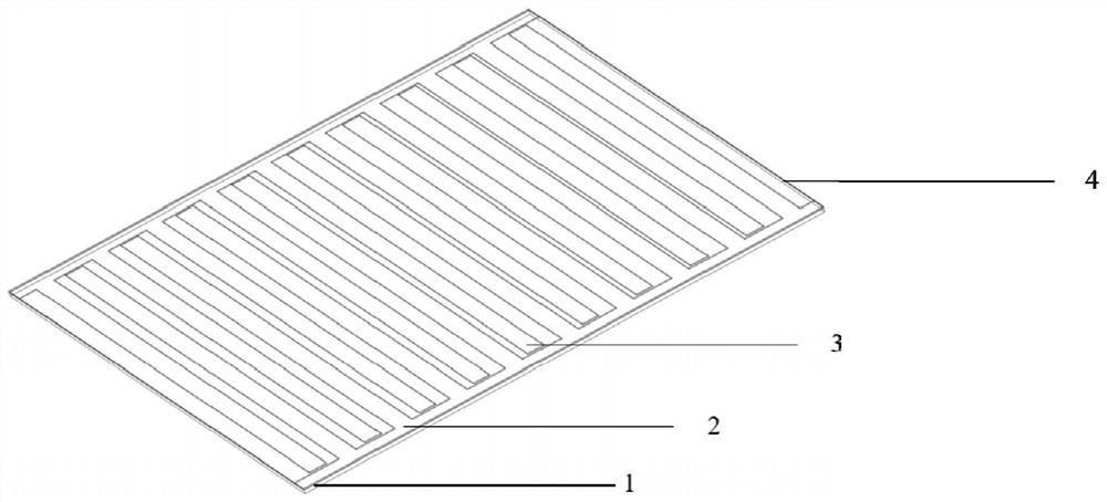
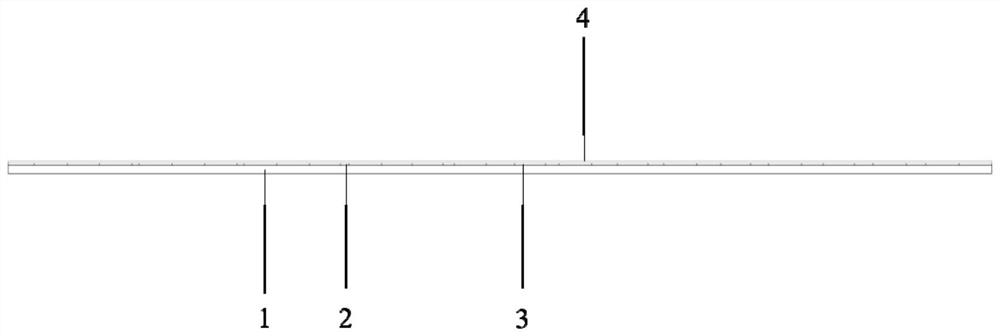
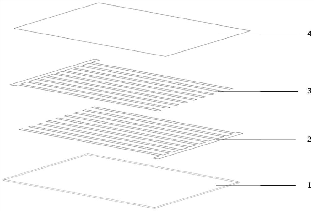
[0018] Example: The use method of electrowetting defogging glass

[0019] When no fog droplets are generated, the glass is used like normal glass. When water vapor in the air condenses or small water droplets splash onto the glass surface, we need to figure 1 An AC voltage is applied across the two electrodes shown to help the droplets coalesce and thus speed up their detachment. Studies have shown that when droplets condense on the surface of ordinary hydrophobic glass, the droplets will be randomly distributed. As time goes by, some small droplets will gradually coalesce into large droplets, but they will still adhere to the glass surface. When we apply an AC voltage between the two electrodes of the AC wetting and defogging glass, the droplets will coalesce and slide down in a very short time, and then clean up the tiny droplets along the way to achieve anti-atomization. Surface cleaning action. Compared with the traditional electric heating defogging method, alternating...


PUM

PropertyMeasurementUnit
thicknessaaaaaaaaaa
thicknessaaaaaaaaaa
thicknessaaaaaaaaaa

Abstract

The invention discloses a method for manufacturing a demisting device by using an alternating current electrowetting principle. The method comprises the following steps: sputtering an indium tin oxide (ITO) conductive layer on the surface of common glass to form a transparent electrode; and spin-coating Teflon on the surface of the transparent electrode and drying to form a hydrophobic layer. The transparent electrodes are a pair of interdigitated electrodes, and the light transmittance of the transparent electrodes is more than 80%. The thickness of the transparent electrode is 10 nm to 1 mm. The thickness of the hydrophobic layer is 0.1 micron to 0.1 mm. According to the method, although the voltage needed by alternating current electrowetting driving is large, the needed current is extremely small, and therefore the power needed by driving is extremely small; as the indium tin oxide electrodes are the transparent electrodes, the device does not cause adverse effects on the light transmission of the glass; the demisting glass has simple and easily available materials and is simple in processing technology, so that the demisting glass can be produced, processed and used on a large scale.

Description

technical field [0001] The invention relates to the field of microfluidic control, in particular to a method for making a demisting device using the principle of alternating current wetting. Background technique [0002] Glass is ubiquitous in our daily life, but when the humidity in the air is high or the temperature is low, under a fixed pressure, when the temperature is lower than the dew point temperature of the air, the water vapor in the air reaches saturation It will then condense into liquid water forming many small water droplets. When small water droplets adhere to the glass, atomization will occur, which will reduce the transparency of the glass, and at the same time, many traces of water droplets will be left after the droplets evaporate. In rainy days, raindrops are easy to touch the glass of the building, which will also make the surface of the glass uneven, and the diffuse reflection of light on the glass surface will reduce the transparency of the glass. In...

Claims


Application Information

Patent Timeline
Patent Type & Authority Applications(China)
IPC IPC(8): B05D5/00B05D7/24C23C14/08C23C14/35
CPCB05D5/00B05D7/24C23C14/086C23C14/35
Inventor 谭杰姜东岳陈贵军田鹏昊
Owner DALIAN UNIV OF TECH
Why Eureka
Try Eureka