Drilling machine capable of automatically ascending and descending drill rod and automatic control method

A technology of automatic drilling and drilling rods, which is applied to drilling equipment and methods, drilling rods, rotary drilling rigs, etc., which can solve the problems of hidden dangers to workers' health and safety, small number of rod replacements, high labor intensity, etc., and achieve easy drilling The effect of pressure relief operation, ensuring the number of drill pipes and reducing the movable space

Pending Publication Date: 2021-11-05
ZOUCHENG TIANHE SCI & TECH
View PDF0 Cites 0 Cited by
  • Summary
  • Abstract
  • Description
  • Claims
  • Application Information

AI Technical Summary

Problems solved by technology

Most of the existing drilling pressure relief construction equipment still relies on people to keep going up and down the drill pipe, which is labor-intensive and low-efficiency, and once an emergency occurs, it is often difficult for on-site construction workers to dodge, which is harmful to the workers. Physical health poses a great safety hazard
[0003] At present, some automatic drilling rigs have appeared, but the number of rod replacements is too small to meet the requirements of anti-scouring and pressure relief drilling depth, and human intervention is still required to change rods, which has not fundamentally solved unmanned drilling.
However, the automatic drilling rig with the required number of replacement rods is too bulky, and many areas with rock burst hazards cannot enter at all. Therefore, a large-capacity, narrow-body automatic drilling rig for automatically loading and unloading drill pipes is urgently needed.

Method used


Image

  • Drilling machine capable of automatically ascending and descending drill rod and automatic control method
  • Drilling machine capable of automatically ascending and descending drill rod and automatic control method
  • Drilling machine capable of automatically ascending and descending drill rod and automatic control method

Examples


Embodiment Construction

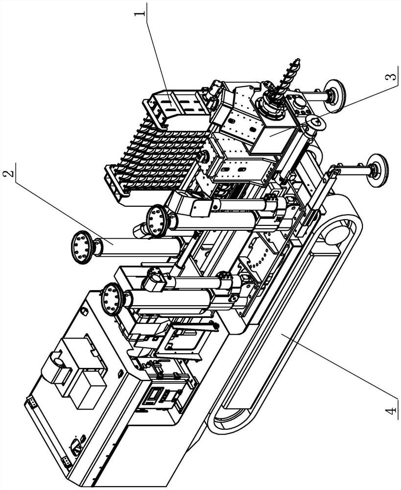
[0041] A kind of drilling rig that can automatically go up and down the drilling rod according to the present invention, such as figure 1 As shown, it includes a chassis walking unit 4, a support device 2, a drill pipe feeding device 3 and an automatic drill pipe box device 1. A support device 2 is installed on the chassis walking unit 4, and a drill pipe feeder is installed on the support device 2 The feeding device 3 is equipped with an automatic drilling rod box device 1 on the drill pipe feeding device 3, wherein the chassis traveling unit 4 can realize the movement of the whole machine in the roadway, and the supporting device 2 can rotate relative to the chassis traveling unit 4 to realize the support of the whole machine At the same time, it can also drive the drill pipe feeding device 3 on it to rotate synchronously, and adjust the position of the pressure relief drilling hole as required. The drill pipe feeding device 3 can move vertically on the support device 2, so a...


PUM


Abstract

The invention discloses a drilling machine capable of automatically ascending and descending a drill rod and an automatic control method. The drilling machine comprises a chassis walking unit, a supporting device, a drill rod feeding device and an automatic drill rod box device, the supporting device is installed on the chassis walking unit, the drill rod feeding device is installed on the supporting device, the automatic drill rod box device is installed on the drill rod feeding device, wherein the supporting device can rotate relative to the chassis walking unit, the drill rod feeding device can vertically move on the supporting device, drill rods in the automatic drill rod box device can automatically go up and down in the drill rod feeding device, the drill rod feeding device can achieve one-by-one drilling and one-by-one retreating of the drill rods, the chassis walking unit comprises a vehicle body, a crawler belt and a walking motor are installed at the bottom of the vehicle body, a walking motor is started to drive the crawler belt to rotate and walk, the automatic drill rod box device comprises a supporting seat, and a drill rod box body is installed on the supporting seat.

Description

technical field [0001] The invention relates to the technical field of underground mining machinery and equipment, in particular to a drilling rig capable of automatically going up and down drilling rods and an automatic control method. Background technique [0002] As a special manifestation of rock pressure, rock burst has become the main disaster in coal mining, especially deep mining. Drilling pressure relief refers to a method of local prevention and control of rock burst by drilling holes in the coal seam impact hazard area to reduce the stress concentration of the coal body. Most of the existing drilling pressure relief construction equipment still relies on people to keep going up and down the drill pipe, which is labor-intensive and low-efficiency, and once an emergency occurs, it is often difficult for on-site construction workers to dodge, which is harmful to the workers. Physical health poses a great safety hazard. [0003] At present, some automated drilling r...

Claims


Application Information

Patent Timeline
IPC IPC(8): E21B7/02E21B15/00E21B19/14E21B19/16E21B19/086E21B19/10E21B3/02
CPCE21B7/021E21B7/024E21B15/003E21B19/14E21B19/164E21B19/086E21B19/10E21B3/02
Inventor 田胜利顾炜炜魏立苏立堂韩欣
Owner ZOUCHENG TIANHE SCI & TECH
Why Eureka
Try Eureka