Non-contact rocker sensor, control device and processing system and method

A non-contact, sensor technology, applied in the field of control devices and processing systems, non-contact rocker sensors, can solve the large deviation of the rotation position of the magnetic sensitive IC chip, the low control accuracy of the rocker potentiometer, and the inability to produce rocker Rod potentiometer and other problems, to achieve the effect of compact structure, large elasticity, small size and light weight

Pending Publication Date: 2021-11-09
GUANGDONG K SILVER IND CO LTD
View PDF2 Cites 5 Cited by
  • Summary
  • Abstract
  • Description
  • Claims
  • Application Information

AI Technical Summary

Problems solved by technology

However, this method of contact adjustment through brushes and carbon resistance generally has the following defects: if a metal with greater elasticity is used as a brush, the brush will wear quickly and have a short service life; When brushing, the contact between the brush and the carbon resistor is prone to poor contact and malfunction; and if a high-hardness carbon resistor is used, the brush will wear out quickly and generate large electrical noise. If a low-hardness carbon resistor is used The carbon powder on the carbon resistor will be worn off by the brush soon, and the carbon powder will stick to the brush, which will affect the electrical performance of the brush and cause the potentiometer to malfunction.
However, this method of detecting the change in the rotational position of the permanent magnet on the upper rocker arm or the lower rocker arm around the rotation axis (structure centerline) through the magnetic sensitive IC chip generally has the following defects: at present, due to the current domestic production of magnetic materials The technology is backward, and there is a large deviation between the central axis of the magnetic force line between the two magnetic poles of the produced magnetic steel and the structural center line of the magnetic steel, so there is a large deviation in the change of the rotation position detected by the magnetic sensitive IC chip, resulting in this vibration. The control accuracy of the rod potentiometer is low, and it cannot be used in practical applications at all, so this kind of magnetic induction rocker potentiometer cannot be produced.

Method used


Image

  • Non-contact rocker sensor, control device and processing system and method
  • Non-contact rocker sensor, control device and processing system and method
  • Non-contact rocker sensor, control device and processing system and method

Examples


Embodiment 1

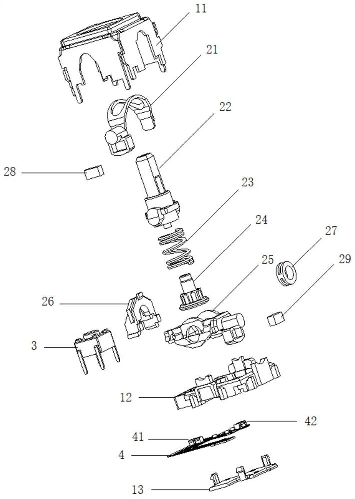
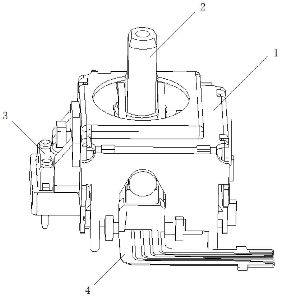
[0072] This embodiment provides a non-contact rocker sensor, such as figure 1 with figure 2 As shown, including rocker assembly 2 and magnetic induction IC assembly 4;

[0073] The rocker assembly 2 includes a first magnet 28 and a second magnet 29, the rocker assembly 2 is used to generate swings in a first direction and a second direction perpendicular to each other, and the first magnet generated following the swing in the first direction The swing of the magnetic field and the swing of the second magnetic field generated by the second magnet following the swing in the second direction; preferably, the first magnet 28 and the second magnet 29 are in the shape of a cuboid or a cube.

[0074] The magnetic induction IC assembly 4 includes a first magnetic induction element 41 and a second magnetic induction element 42, which are used to generate the first electrical signal corresponding to the change in the distance between the first magnet and the first magnetic induction e...

Embodiment 2

[0109] This embodiment provides a control device, including the non-contact joystick sensor in Embodiment 1, which can be used as a control component for drones, game machines, and the like.

Embodiment 3

[0111] This embodiment provides a non-contact rocker sensor processing method, such as Figure 14 shown, including the following steps:

[0112] S1. Respectively obtain the end values ​​of the swing angles in the first direction and the second direction of the non-contact rocker sensor in Embodiment 1 and the end values ​​of the output voltages corresponding to the end values ​​of the swing angles; preferably, the end values ​​of the swing angles include Leftmost swing angle end value, upright swing angle end value and rightmost swing angle end value;

[0113] S2. Establish an optimization model:

[0114] minw=||u k1 (ω, θ 1 , t 1 ,ε)-u k2 (ω, θ 2 , t 2 ,ε)|-|u k3 (ω, θ 2 , t 3 ,ε)-u k4 (ω, θ 1 , t 4 ,ε)||

[0115] Among them, ω is the swing speed of the rocker in the first direction (or the second direction), ε is the error parameter, θ 1 is the first angle of the joystick in the first direction (or the second direction), θ 2 is the second angle of the rocker ...


PUM


Abstract

The invention discloses a non-contact rocker sensor, a control device and a processing system and method, and relates to the technical field of novel sensors. The non-contact rocker sensor comprises a rocker assembly and a magnetic induction IC assembly. The rocker assembly is used for generating swing in a first direction and a second direction which are perpendicular to each other, swing of a first magnetic field generated by a first magnet swinging in the first direction and swing of a second magnetic field generated by a second magnet swinging in the second direction. The magnetic induction IC assembly is used for generating and outputting a first electric signal corresponding to the change of the distance between the first magnet and the first magnetic induction element caused by the swing of the first magnet and a second electric signal corresponding to the change of the distance between the second magnet and the second magnetic induction element caused by the swing of the second magnet. The non-contact rocker sensor has the advantages of long service life, high control precision and small size.

Description

technical field [0001] The invention relates to the technical field of new sensors, in particular to a non-contact rocker sensor, a control device, and a processing system and method. Background technique [0002] The joystick sensor is a kind of sensor, which is often used as a drone operating handle, game handle, etc. The rocker sensor mainly includes a rocker and two swing arm components, and the rocker is moved to drive the swing arm components to operate, so that the potential adjustment module can output a specific resistance or voltage. [0003] There are mainly two types of existing rocker sensors. One is composed of brushes, circuit boards, and carbon resistors arranged on the circuit boards. External forces make the brushes move on the carbon resistors to produce different vibrations on the circuit board. The resistance value, and then the electrical signals generated by different resistance values ​​are different to achieve the effect of using the rocker sensor t...

Claims


Application Information

Patent Timeline
Patent Type & Authority Applications(China)
IPC IPC(8): G01D5/14G01D11/24G05B13/04
CPCG01D5/142G01D11/24G05B13/042
Inventor 曾晓赵建波
Owner GUANGDONG K SILVER IND CO LTD
Why Eureka
Try Eureka