Melting-brazing composite weld joint of weathering resistant steel and welding method of melting-brazing composite weld joint
A composite welding seam and welding method technology, applied in welding equipment, metal processing equipment, manufacturing tools, etc., can solve the problems of slow sealing bottom layer, high cost of stainless steel, no advantages in cost and production efficiency, etc., and achieve high production efficiency, Excellent weather resistance, saving welding passes
- Summary
- Abstract
- Description
- Claims
- Application Information
AI Technical Summary
Problems solved by technology
Method used
Image
Examples
Embodiment 1
[0037] Example 1: 4mm thick steel plate butt joint
[0038] The soldering steps are as follows:
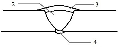
[0039] Step 1: Make a V-shaped groove on the plate to be welded, the groove angle is 70°, and the blunt edge is 1mm, such as figure 1 shown;
[0040] Step 2: Grind the groove of the welded plate and the 25mm range on both sides until the metallic luster is exposed;
[0041] Step 3: Assemble 1.2mm specification 4043 aluminum-silicon welding wire at the blunt edge position, and perform spot welding positioning after the welding wire is clamped;
[0042] Step 4: Using CO 2 Gas shielded welding is used to weld the filling layer. The welding wire is THQ-60C low-alloy steel welding wire with a diameter of 1.2mm. This welding wire meets the requirements of the ER60-G welding wire specified in the national standard GB / T 8110-2008; The welding speed is 38cm / min, and the welding heat input is 7.29kJ / cm.
[0043] Step 5: At CO 21.2mm specification 4043 aluminum-silicon welding wire is ...
Embodiment 2
[0044] Example 2: Butt joint of 6mm thick steel plates
[0045] The soldering steps are as follows:
[0046] Step 1: Make a V-shaped groove on the plate to be welded, the groove angle is 55°, and the blunt edge is 1.5mm, such as figure 1 shown;
[0047] Step 2: Grind the groove of the welded plate and the 25mm range on both sides until the metallic luster is exposed;
[0048] Step 3: Assemble 1.2mm specification 4043 aluminum-silicon welding wire at the blunt edge position, and perform spot welding positioning after the welding wire is clamped, such as figure 1 shown;
[0049] Step 4: Using CO 2 The gas shielded welding is used to weld the filling layer separately. The welding wire is THQ-60D low-alloy steel welding wire with a diameter of 1.2mm. The voltage is 25V, the welding speed is 29cm / min, and the welding heat input is 12.16kJ / cm.
[0050] Step 5: At CO 2 1.2mm specification 4045 aluminum-silicon welding wire is fed at 10mm behind the gas shielded welding torch, ...
Embodiment 3
[0051] Example 3: Butt joint of 9mm thick steel plates
[0052] The welding steps are as follows
[0053] Step 1: Make an X-shaped bevel on the plate to be welded, the bevel angle is 60°, and the blunt edge is 1mm, such as image 3 shown;
[0054] Step 2: Grind the groove of the welded plate and the 25mm range on both sides until the metallic luster is exposed;
[0055] Step 3: Perform tack welding on the welding plate, and reserve a groove gap of 0.5~1mm;
[0056] Step 4: Using CO 2 Gas shielded welding is used to weld the filling layer on both sides. The welding wire is THQ-60C low-alloy steel welding wire with a diameter of 1.2mm. , welding voltage 23~24V, welding speed 32~33cm / min, welding heat input 9.4~9.9kJ / cm.
[0057] Step 5: At CO 2 The 1.2mm specification 4045 aluminum silicon welding wire is filled at 13mm behind the gas shielded welding torch. At the same time, argon gas purging is used to promote the wetting of the filling layer. The welding voltage is 14V...
PUM
| Property | Measurement | Unit |
|---|---|---|
| thickness | aaaaa | aaaaa |
Abstract
Description
Claims
Application Information
 - R&D
- Intellectual Property
- Life Sciences
- Materials
- Tech Scout
- Unparalleled Data Quality
- Higher Quality Content
- 60% Fewer Hallucinations
Browse by: Latest US Patents, China's latest patents, Technical Efficacy Thesaurus, Application Domain, Technology Topic, Popular Technical Reports.
© 2025 PatSnap. All rights reserved.Legal|Privacy policy|Modern Slavery Act Transparency Statement|Sitemap|About US| Contact US: help@patsnap.com


