Bolt fault diagnosis method and device
A fault diagnosis device and fault diagnosis technology, applied in the direction of measuring devices, mechanical devices, mechanical measuring devices, etc., can solve the problems of bolt group monitoring, fault diagnosis, and inability to effectively diagnose bolts, etc., to achieve a wide range of applications and improve self-adaptation ability, ease of statistical analysis and modeling of effects
- Summary
- Abstract
- Description
- Claims
- Application Information
AI Technical Summary
Problems solved by technology
Method used
Image
Examples
Embodiment 1
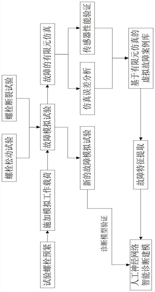
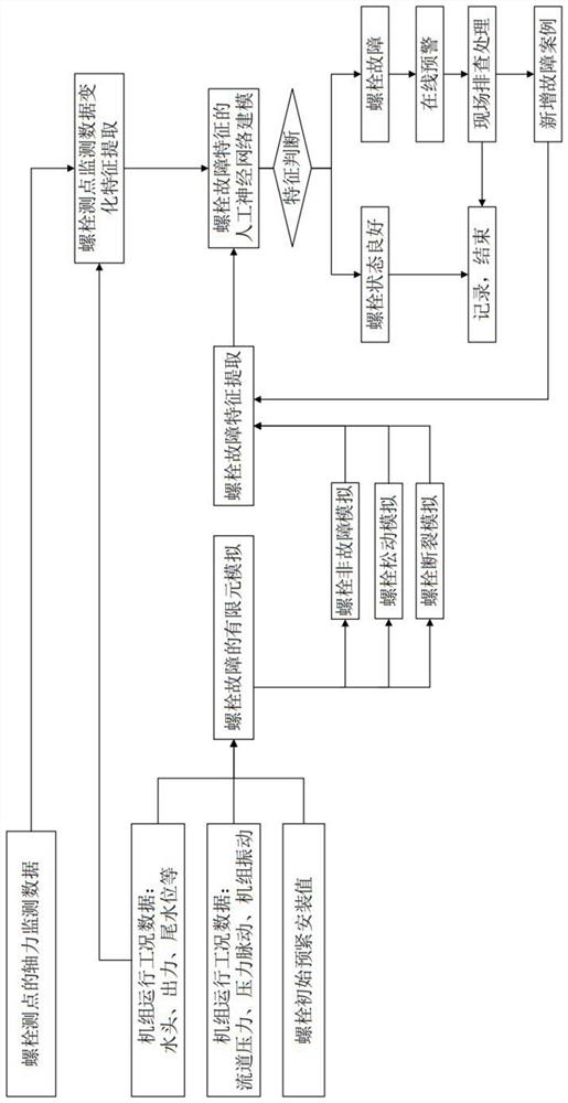
[0050] Such as Figure 1 to Figure 5 As shown, a bolt fault diagnosis method includes the following steps:
[0051] S1, carry out the bolt failure simulation test, and record the monitoring data of the bolt failure monitoring point;
[0052] S2, simulating bolt faults through the finite element method, and establishing a virtual fault case library;
[0053] S3, extract the fault features in the virtual fault case library, and perform artificial intelligence modeling on the bolt fault of the real machine.
[0054] The present invention solves the problems of limited number of bolt fault monitoring points, limited arrangement of bolt fault monitoring points, and rapid diagnosis of fault points through bolt fault simulation tests, fault simulation, artificial intelligence modeling, and the like. Through the finite element simulation, the virtual fault case library is established, and the automatic diagnosis of the bolt faults of the real machine can be realized, which is convenie...
Embodiment 2
[0066] Such as Figure 1 to Figure 5 As shown, as a further optimization of Embodiment 1, this embodiment includes all the technical features of Embodiment 1. In addition, this embodiment also includes the following technical features:
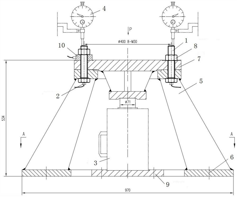
[0067] A bolt fault diagnosis device applied to the bolt fault diagnosis method described above includes a bolt 1 , a bolt axial force monitoring instrument 2 connected to the bolt 1 , and a load simulation device 3 connected to the bolt 1 .
[0068] The load simulation device 3 provides simulated loads for the failure of the bolt 1, and the bolt axial force monitoring instrument 2 monitors the bolt axial force in the process of the failure of the bolt 1 in real time, so as to facilitate the diagnosis of the failure of the bolt 1.
[0069] As a preferred technical solution, the load simulation device 3 is a jack.
[0070] The jack applies loads well and is easy to install.
[0071] As a preferred technical solution, the bolt axial force moni...
Embodiment 3
[0076] Such as Figure 1 to Figure 5 As shown, on the basis of Embodiment 1 and Embodiment 2, this embodiment provides a more detailed implementation manner.
[0077] The fault simulation device consists of base 5, base fixing bolt 6, flange 7, test bolt (i.e. bolt 1), test nut 8, jack (i.e. load simulation device 3), jack support plate 9, dial indicator (i.e. Bolt length monitoring instrument 4), bolt force sensor (ie bolt axial force monitoring instrument 2), force measuring washer 10, see figure 1 .
[0078] When in use, the base 5 is fixed on the test bench by the base fixing bolt 6; the flange 7 is connected to the base 5 according to the set preload by the test bolt and the test nut; the external load of the work is accurately simulated by the jack . The bolt force sensor is consistent with the real machine, and the ultrasonic force sensor is preferred. The elongation value of the test bolt is monitored by a dial gauge.
[0079] The test bolts of this device are 8 M...
PUM
 Abstract
Description
Claims
Application Information
 - R&D
- Intellectual Property
- Life Sciences
- Materials
- Tech Scout
- Unparalleled Data Quality
- Higher Quality Content
- 60% Fewer Hallucinations
Browse by: Latest US Patents, China's latest patents, Technical Efficacy Thesaurus, Application Domain, Technology Topic, Popular Technical Reports.
© 2025 PatSnap. All rights reserved.Legal|Privacy policy|Modern Slavery Act Transparency Statement|Sitemap|About US| Contact US: help@patsnap.com


