Zero-crossing pulse counting open-phase detection circuit
A phase loss detection and zero-crossing pulse technology, applied in the direction of asymmetric measurement of multi-phase networks, can solve the problems of voltage detection circuit interference, missed reporting accidents, device burnout, etc., to achieve improved accuracy, convenient operation and low cost. Effect
- Summary
- Abstract
- Description
- Claims
- Application Information
AI Technical Summary
Problems solved by technology
Method used
Image
Examples
Embodiment 1
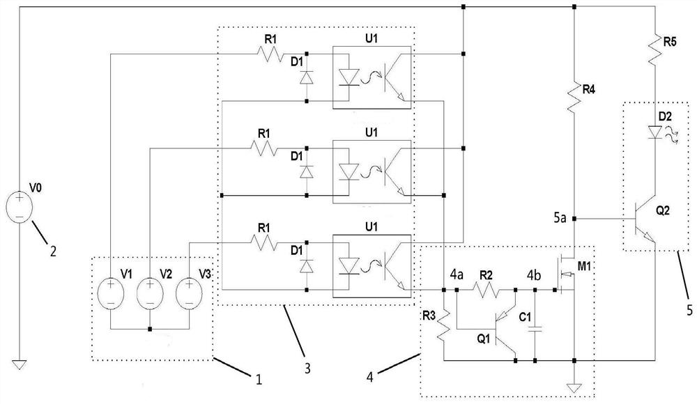
[0029] Such as figure 1 As shown, a zero-crossing pulse counting phase loss detection circuit includes a three-phase power supply 1, a DC source 2, three conversion modules 3, a counting module 4, and an alarm module 5. Wherein, the three-phase power supply 1 can output power frequency three-phase alternating current, and the three-phase power supply 1 is connected to the detection terminal of the conversion module 3 through a three-phase half-bridge rectifier circuit composed of three voltage dividing resistors R1 and three rectifier diodes D1. Three-phase half-wave detection signals are output, and the three-phase power supply 1 also drives the three-phase motor through the branch circuit; the positive poles of the three optocouplers U1 of the conversion module 3 are respectively connected to one phase of the three-phase power supply 1 through the voltage dividing resistor R1, The negative poles of the three optocouplers U1 are connected to each other, and the collectors of ...
Embodiment 2
[0036] The difference between this embodiment and the first embodiment is that the rectifier diode D1 is eliminated, and the type of the optocoupler U1 is limited to the AC optocoupler U1, so as to directly implement accurate detection of the three-phase full-wave signal and expand the implementation type accordingly.
[0037] The circuit of this embodiment only needs to figure 1 The shown rectifier diode D1 is canceled, and then the type of optocoupler U1 is limited to AC optocoupler U1, so that the three-phase full-wave signal is directly input to the detection terminals of the three AC optocouplers U1. At this time, the optical receiver of optocoupler U1 will The full-wave signal is converted into a photocurrent pulse, which is the same as the embodiment. When the three-phase power supply 1 has a phase loss fault, even if there is a load interference potential, the pulse of the counting terminal 4a can be zero-crossed, and the alarm module 5 is triggered by the discharge of ...
Embodiment 3
[0042] The difference between this embodiment and the first embodiment is that the feedback module 6 is added, so as to realize the automatic maintenance function of phase loss and cut-off for the three-phase load 7 .
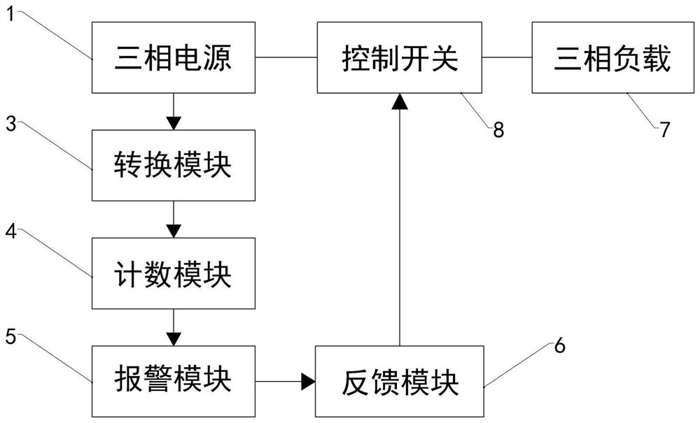
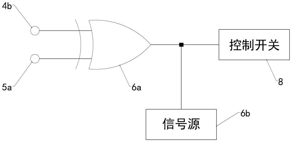
[0043] Such as figure 2 As shown, the trigger terminal 5a of the alarm module 5 is also connected to the detection terminal of a feedback module 6, while the excitation terminal of the feedback module 6 is connected to the control switch 8 of the three-phase load 7 connected to the three-phase power supply 1 The three-phase load 7 is a three-phase motor, and is connected to the three-phase power supply 1 through a three-phase four-wire connection, and the control switch 8 is an electronic relay.
[0044] The working principle of this embodiment is as follows:
[0045] When the three-phase power supply 1 is in normal operation, the low level of the trigger terminal 5a of the alarm module 5 makes the feedback module 6 in a standby state; when the three-phase po...
PUM
 Abstract
Description
Claims
Application Information
 - R&D
- Intellectual Property
- Life Sciences
- Materials
- Tech Scout
- Unparalleled Data Quality
- Higher Quality Content
- 60% Fewer Hallucinations
Browse by: Latest US Patents, China's latest patents, Technical Efficacy Thesaurus, Application Domain, Technology Topic, Popular Technical Reports.
© 2025 PatSnap. All rights reserved.Legal|Privacy policy|Modern Slavery Act Transparency Statement|Sitemap|About US| Contact US: help@patsnap.com


