Drying device and drying method

Pending Publication Date: 2021-11-23
NANCHANG HANGKONG UNIVERSITY
View PDF9 Cites 3 Cited by
  • Summary
  • Abstract
  • Description
  • Claims
  • Application Information

AI Technical Summary

Problems solved by technology

[0012] The purpose of the present invention is to provide a drying device and a drying method to solve the above-mentioned problems in the prior art, and to solve the problem that the tail gas contains non-condensable gas and the heat exchange efficiency of tail gas waste heat is low.

Method used


Image

  • Drying device and drying method

Examples


Embodiment 1

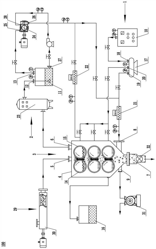
[0046] Such as figure 1 As shown: this embodiment provides a drying device 100, the material to be dried is wet sludge, including a drying system 1 and a steam recovery system 2, the drying system 1 includes a dryer 3 and a steam generator 10, and the dryer 3 includes The drying chamber 4 and the drier arranged inside the drying chamber 4, the drying machine 3 adopts a vertical layout, the top of the drying chamber 4 is provided with a feed inlet 5 and an exhaust gas outlet 6, and the bottom of the drying chamber 4 is provided with a discharge port 7, The steam convection drying inlet 8 and the air outlet 9, the steam convection drying inlet 8 and the drier are all communicated with the steam generator 10, and the steam recovery system 2 includes a separation buffer tank 11, which is used to separate water and steam , the tail gas outlet 6 communicates with the inlet 12 of the separation buffer tank 11, and the gas outlet 13 of the separation buffer tank 11 communicates with t...

Embodiment 2

[0064] This embodiment provides a drying method using the drying device 100 of Embodiment 1, comprising the following steps:

[0065] Step 1, open the control valve between the steam generator 10 and the air sub-cylinder 17, start the steam generator 10, and open between the sub-air cylinder 17 and the first thermal compensator 21, between the sub-air cylinder 17 and each group of rollers after generating steam The control valve in between starts the first thermal compensator 21, heats the convective drying steam, and passes the steam into the dryer 3, so that the dryer 3 is preheated, and the air in the dryer 3 is exhausted;

[0066] Step 2, start the delivery pump 30, and the sludge enters the dryer 3 through the feed port 5 at the top of the drying chamber 4;

[0067] Step 3: The sludge is dried from top to bottom by heat conduction through counter rolls with saturated steam, and at the same time, the sludge is thermally convectively dried from bottom to top by the convecti...


PUM


Abstract

The invention discloses a drying device and a drying method, and relates to the technical field of drying equipment. The drying device comprises a drying system and a steam recovery system, the drying system comprises a drying machine and a steam generator, the drying machine comprises a drying chamber and a dryer arranged in the drying chamber, a feeding port and a tail gas outlet are formed in the top of the drying chamber, a discharging port, a steam convection drying air inlet and an air outlet are formed in the bottom of the drying chamber, the steam convection drying air inlet and the dryer both communicate with the steam generator, and the steam recovery system comprises a separation buffer tank. The separation buffer tank is used for separating water and steam, the tail gas outlet communicates with an air inlet of the separation buffer tank, and an air outlet of the separation buffer tank respectively communicates with the steam convection drying air inlet and the dryer. The problem that the heat exchange efficiency of tail gas waste heat utilization is low due to the fact that dry tail gas contains non-condensable gas is solved.

Description

technical field [0001] The invention relates to the technical field of drying equipment, in particular to a drying device and a drying method. Background technique [0002] With the increasing urbanization and modernization of the world, the amount of urban wastewater and industrial wastewater is also increasing, and the amount of sludge as a by-product of wastewater treatment is also increasing sharply. If the sludge is not properly disposed of, not only will it cause secondary pollution to the environment, but the harmful components in the sludge will also damage human health. Therefore, the harmless and reduced treatment of sludge is particularly important. Reducing the water content in sludge is an effective way to reduce the amount of sludge. An effective way to reduce the water content is to use heat energy to evaporate the water in the sludge to achieve the purpose of rapid drying. In the process of sludge drying, drying equipment, energy consumption, drying rate and...

Claims


Application Information

Patent Timeline
Patent Type & Authority Applications(China)
IPC IPC(8): C02F11/13
CPCC02F11/13
Inventor 张绪坤傅伟良张城镇邢普李康康吴鹏辉甘茂云周文华邹雪平彭福明
Owner NANCHANG HANGKONG UNIVERSITY
Why Eureka
Try Eureka