
Circuit protection monitor for battery-powered servo control system

A servo control system and circuit protection technology, applied in the field of power equipment, can solve problems such as surge voltage and current impact, DC bus voltage increase, etc., and achieve the effects of extending service life, reducing volume, and protecting communication security.

Pending Publication Date: 2021-11-23
BEIJING E MOTION CONTROL EQUIP TECH
View PDF0 Cites 0 Cited by
  • Summary
  • Abstract
  • Description
  • Claims
  • Application Information

AI Technical Summary

Problems solved by technology

[0004] The surge voltage and current impact of the DC power supply system inside the existing circuit protection monitor at the moment of power-on;
[0005] And in the DC power supply system, when there is an instantaneous conversion of mechanical energy into electrical energy, the DC bus voltage will increase;

Method used


Image

  • Circuit protection monitor for battery-powered servo control system
  • Circuit protection monitor for battery-powered servo control system
  • Circuit protection monitor for battery-powered servo control system

Examples


Embodiment 1

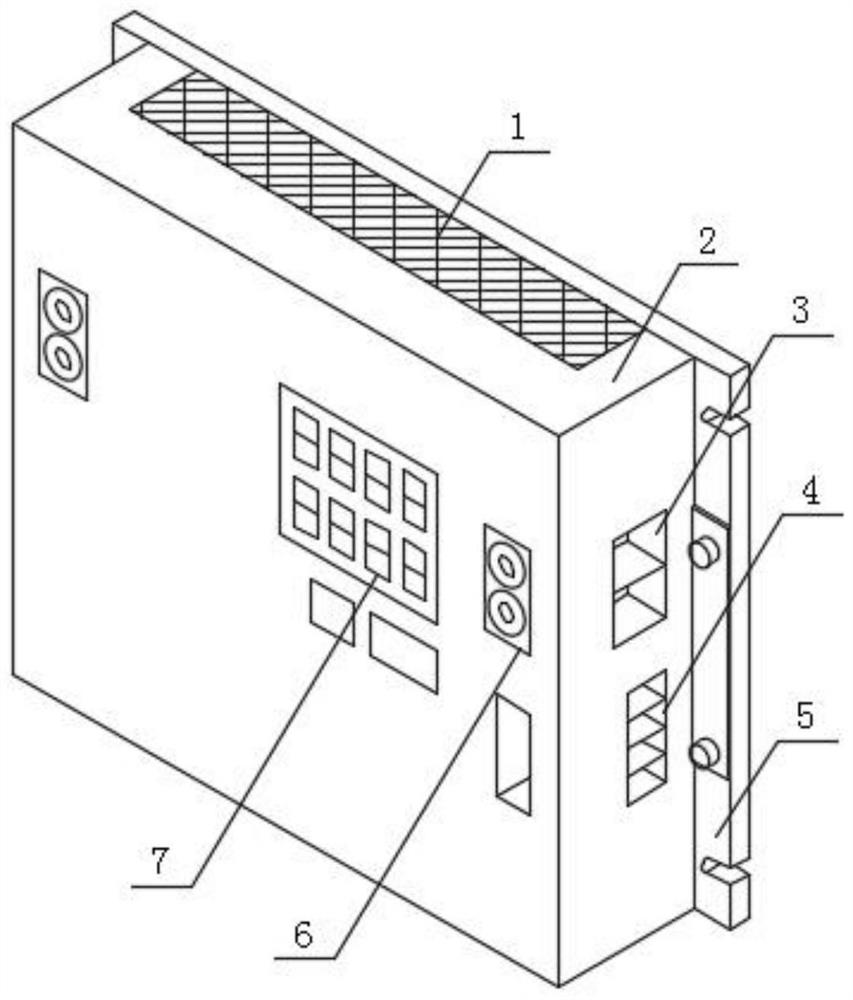
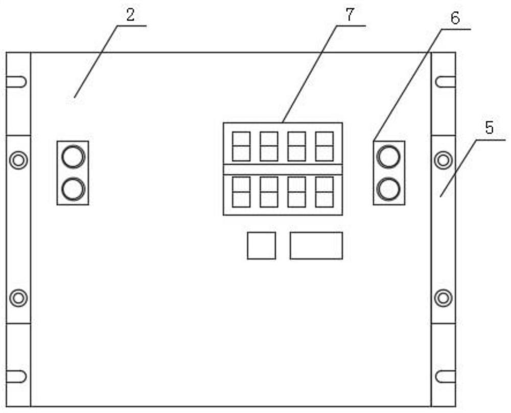
[0035] Such as figure 1 , figure 2 , image 3 and Figure 4 As shown, a circuit protection monitor for a battery-powered servo control system includes a protection monitor body 2, a connecting plate 5 is installed at the rear end of the protection monitor body 2, and the upper and lower sides of the protection monitor body 2 are respectively A heat dissipation window 1 is installed, a first socket 3 is installed on one side of the protective monitor main body 2, a second socket 4 is installed below the first socket 3, and an operation panel 7 is installed on the front surface side of the protective monitor main body 2 , a third socket 6 is installed on both sides of the operation screen 7;

[0036] The main body 2 of the protection monitor is composed of a bright LED display module 21, an anti-surge soft start module 22, a pre-charge module 23, a housing 24, an anti-DC bus overvoltage braking energy consumption module 25, a power output protection module 26, and a CANBUS h...

Embodiment 2

[0038] Such as figure 1 , figure 2 , image 3 As shown, the connecting plate 5 is a plate-shaped structure, and the connecting plate 5 and the protection monitor main body 2 are provided with screw rods at the axis of both sides, and the upper and lower sides of the screw rod are respectively recessed with a hole.

[0039] During specific use, the main body 2 of the protection monitor can be easily installed through the arrangement of the connecting plate 5 .

Embodiment 3

[0041] Such as figure 1 , figure 2 , image 3 As shown, the heat dissipation window 1 is a rectangular plate structure, and the heat dissipation window 1 is respectively installed on the upper and lower ends of the protection monitor main body 2 by screws, and the intersection of the protection monitor main body 2 and the heat dissipation window 1 is concaved with a rectangular hole.

[0042] In specific use, this can make the installation of the heat dissipation window 1 and the main body of the protective monitor 2 more convenient and quick.


PUM


Abstract

The invention discloses a circuit protection monitor for a battery-powered servo control system. The circuit protection monitor comprises a protection monitor body, a connecting plate is mounted at the rear end of the protection monitor body, and a heat dissipation window is installed on each of the upper and lower sides of the protection monitor body. According to the device, a plurality of groups of IGBTs connected in parallel are used in an anti-surge soft starting module inside the device to replace a traditional relay or contactor, so that the product size is reduced, the noise is reduced, the energy consumption is reduced, and the service life is prolonged. According to the device, a comprehensive CAN BUS high-speed bus communication module is adopted, various baud rates and communication ID combinations can be configured, the device adapts to a personalized scheme of a customer, and the communication safety of a product and a customer bus is protected by adopting an isolated communication design. According to the device, through various customized protection voltage settings, a built-in brake module consumes impact energy, and a client energy consumption resistor can be externally connected, so that the use flexibility of the product is improved.

Description

technical field [0001] The invention belongs to the technical field of electric equipment, in particular to a circuit protection monitor for a battery-powered servo control system. Background technique [0002] In a battery-powered servo system, because there is a large-capacity capacitor in the back-end load, the low-voltage DC power supply will instantly charge both ends of the capacitor when the system is powered on. Equivalent to a short circuit state. The instantaneous short-circuit state will cause the output current of the DC power supply to soar to hundreds of amperes to thousands of amperes, and the instantaneous high-current impact will cause the power supply protection to have no output, and will also cause the subsequent load to stop working. [0003] In a battery-powered servo system, if there are electric actuators in the system, when these devices are in the process of emergency deceleration or braking, the mechanical energy will be converted into electrical ...

Claims


Application Information

Patent Timeline
IPC IPC(8): H02H9/02H02H9/04H04L12/40
CPCH02H9/02H02H9/04H04L12/4013H04L2012/40215Y02D30/50
Inventor 高满元梁丽君李恒
Owner BEIJING E MOTION CONTROL EQUIP TECH
Learn More