Multi-port energy storage energy router

A router and multi-port technology, applied in the direction of circuit devices, AC network circuits, single AC networks with different frequencies, etc., can solve the problems of single energy supply type, single port type, high manufacturing cost, etc., to achieve comprehensive port types and improve Safety, avoidance of economic losses and effects of safety accidents

Pending Publication Date: 2021-11-23
成都星宇融科电力电子股份有限公司
View PDF0 Cites 0 Cited by
  • Summary
  • Abstract
  • Description
  • Claims
  • Application Information

AI Technical Summary

Problems solved by technology

[0007] In order to solve the problems of large current loss, serious heat generation, high manufacturing cost, too single port type, poor functionality, single energy supply type, poor stability and low safety existing in the prior art, the purpose of the present invention is to provide a multi-port energy storage energy router

Method used


Image

  • Multi-port energy storage energy router
  • Multi-port energy storage energy router
  • Multi-port energy storage energy router

Examples


Embodiment 1

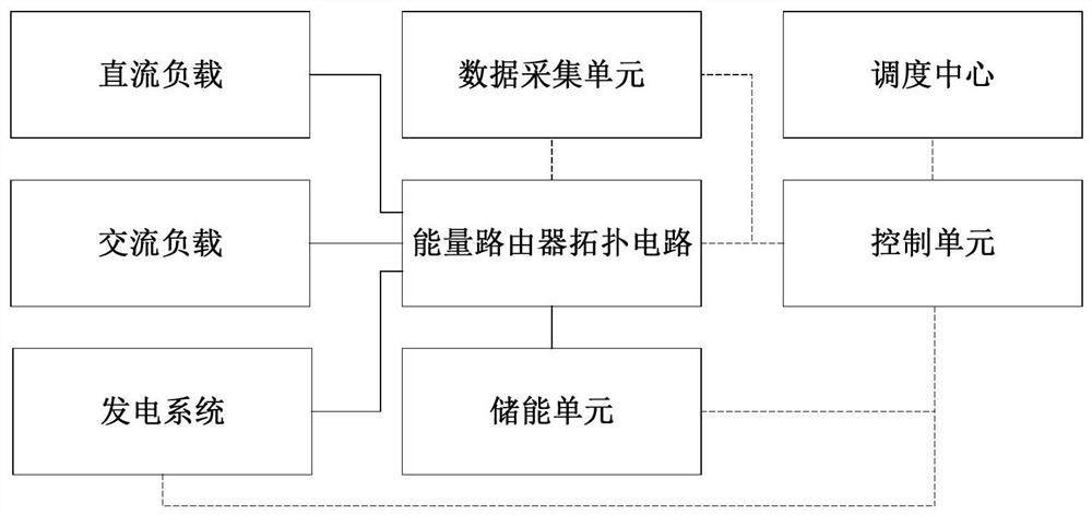
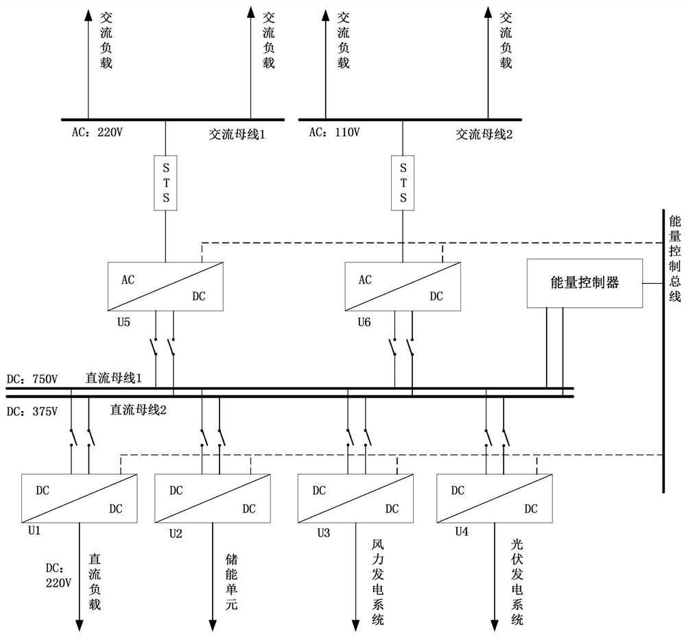
[0034] like figure 1 As shown, this embodiment provides a multi-port energy storage energy router, including an energy router topology circuit with multiple ports, a control unit, and an energy storage unit. One end of the energy router topology circuit is electrically connected to a dual DC bus, and the energy The other end of the router topology circuit is electrically connected to the energy storage unit, and this end is electrically connected to the load and the power generation system through several access ports, and the control unit is respectively connected to the energy router topology circuit, the energy storage unit and the power generation system in communication, and The control unit is connected to a dispatch center, and the dual DC bus includes two DC buses with different DC voltage levels;

[0035] The dispatching center collects the electric energy operation data of the topological circuit of the energy router, and controls the electric energy transmission bet...

Embodiment 2

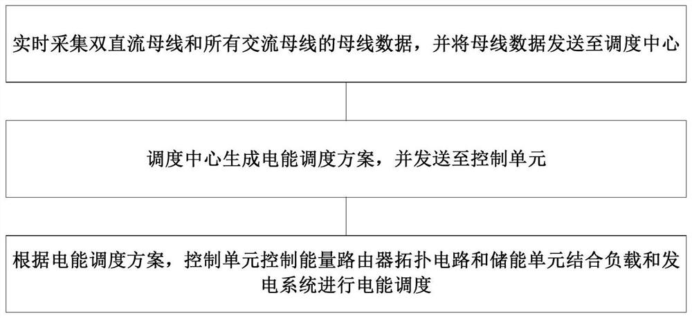
[0051] like image 3 As shown, on the basis of Embodiment 1, this embodiment provides a multi-port energy storage energy router power scheduling method. Based on the energy storage energy router, the method includes the following steps:

[0052] Collect the bus data of dual DC bus and all AC buses in real time, and send the bus data to the dispatch center;

[0053] The dispatch center generates a power dispatch plan and sends it to the control unit;

[0054] According to the electric energy dispatching scheme, the control unit controls the energy router topology circuit and the energy storage unit to carry out electric energy dispatching in combination with the load and the power generation system.

[0055] Preferably, the electric energy scheduling scheme includes: a single-port electric energy scheduling scheme and a multi-port electric energy scheduling scheme, and the single-port electric energy scheduling scheme includes: grid-charge energy scheduling, source-charge ener...


PUM


Abstract

The invention belongs to the technical field of energy routers, and discloses a multi-port energy storage energy router, which comprises a multi-port energy router topology circuit, a control unit and an energy storage unit. The energy router topology circuit is provided with double direct current buses and an alternating current bus group, and is electrically connected with the energy storage unit; and the energy router topology circuit is electrically connected with a load and a power generation system through a plurality of access ports, the control unit is in communication connection with the energy router topology circuit, the energy storage unit and the power generation system, and the control unit is in communication connection with a dispatching center. The problems that in the prior art, current loss is large, heating is serious, the manufacturing cost is high, the port type is too single, functionality is poor, the energy supply type is single, stability is poor, and safety is low are solved.

Description

technical field [0001] The invention belongs to the technical field of energy routers, and in particular relates to a multi-port energy storage energy router. Background technique [0002] "Energy router" is defined as: an intelligent body with computing, communication, precise control, remote coordination, autonomy, and plug-and-play access versatility that integrates the cyber-physical system of the power grid. It has the following basic characteristics: adopts a fully flexible architecture Solid-state equipment; it has the functions of traditional transformers, circuit breakers, power flow control devices and power quality control devices; it can realize AC and DC seamless mixed power distribution; distributed power supply, flexible load (distributed energy storage, electric vehicle) device Plug and play access; intelligent control unit with information fusion to realize autonomous distributed control operation and energy management; integrated strong communication networ...

Claims


Application Information

Patent Timeline
Patent Type & Authority Applications(China)
IPC IPC(8): H02J3/38H02J3/02H02J3/28H02J3/32H02J3/06
CPCH02J3/381H02J3/02H02J3/28H02J3/32H02J3/06H02J2203/10H02J2203/20H02J2300/20
Inventor 何周平柴若愚陈洪才
Owner 成都星宇融科电力电子股份有限公司
Why Eureka
Try Eureka