Welding working condition purification fan

A technology for purifying fans and welders. It is used in welding equipment, auxiliary welding equipment, welding/cutting auxiliary equipment, etc. It can solve the problems of failure of fire protection devices, easy blocking of fire protection devices, and excessive dust, so as to prevent fires and improve the impact of sparks. rate effect

Pending Publication Date: 2021-12-03
SUZHOU DONGSHAN PRECISION MANUFACTURING CO LTD
View PDF0 Cites 1 Cited by
  • Summary
  • Abstract
  • Description
  • Claims
  • Application Information

AI Technical Summary

Problems solved by technology

[0003] Defects of existing technology: At present, fans are used in welding conditions, and there are purification equipment such as filter cartridges and cloth bags. The filter cartridges are consumables and generally need to be replaced after 6 months to 1 year of use. Some equipment needs to be maintained and updated even in 1 month; During the normal use of some equipment, pollutants (dust and oil) will be absorbed in the cooling box due to inhalation; there is a large amount of spark spatter in welding conditions, and when sparks pass through the pipeline or equipment, they are not cooled well and will ignite the purification equipment Dust or oil pollutants in the air; some equipment on the market has added a fire protection device, but the welding condition is dusty, which is easy to block the fire protection device, thus making the fire protection device invalid

Method used


Image

  • Welding working condition purification fan
  • Welding working condition purification fan
  • Welding working condition purification fan

Examples


Embodiment Construction

[0027] The technical solutions of the present invention will be clearly and completely described below through specific embodiments. Apparently, the described embodiments are only some of the embodiments of the present invention, but not all of them. Based on the embodiments of the present invention, all other embodiments obtained by persons of ordinary skill in the art without creative efforts fall within the protection scope of the present invention.

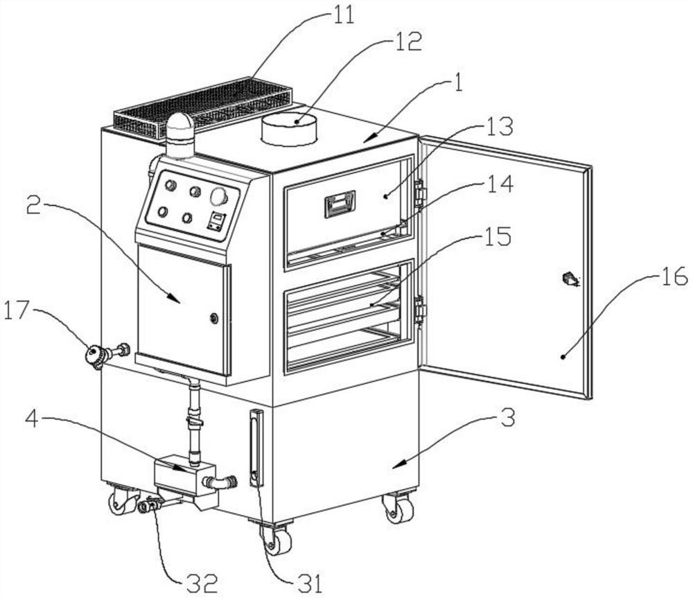
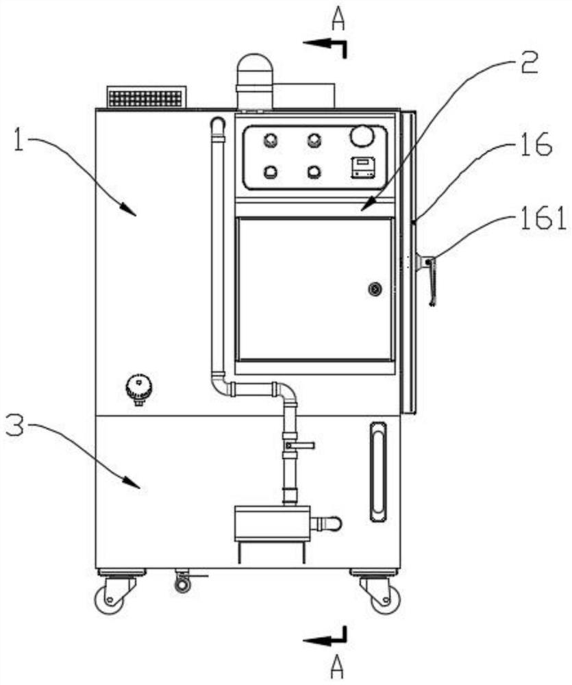
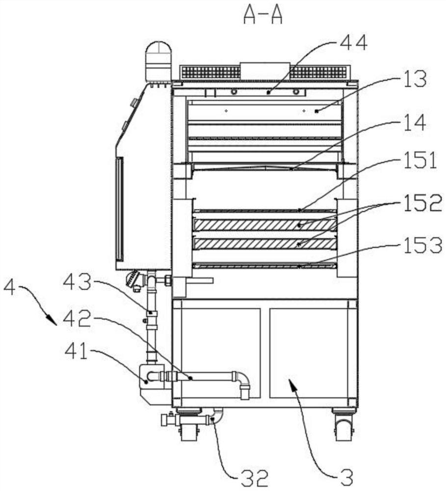
[0028] refer to figure 1 and figure 2 , a purification fan under welding conditions, including a chassis 1, a water tank 3, a spray assembly 4, and an electric cabinet 2, the electric cabinet 2 is fixedly connected to one side of the chassis 1, and the top of the chassis 1 is provided with an air inlet pipe 12, and the air inlet pipe 12 One side is fixedly connected with a fan 11 communicating with the inside of the chassis 1, and the upper layer inside the chassis 1 is fixedly connected with a cooling box 13, a particle co...


PUM


Abstract

A welding working condition purification fan comprises a machine box, a water tank, a spraying assembly and an electric cabinet. The electric cabinet is fixedly connected to one side of the machine box, an air inlet pipe is arranged at the top of the machine box, a fan body communicating with the interior of the machine box is fixedly connected to one side of the air inlet pipe, and a cooling box is fixedly connected to the upper layer of the interior of the machine box. A particle collecting box is arranged at the bottom of the cooling box, a filter plate set is arranged at the bottom of the particle collecting box, the water tank is fixedly connected to the bottom of the machine box, the spraying assembly is fixedly connected to one side of the machine box, and the water suction end of the spraying assembly extends into the water tank. The water outlet end of the spraying assembly extends into the machine box and is arranged above the cooling box, and a machine box water outlet valve is arranged at the bottom of one side of the machine box. The welding working condition purification fan is provided with the spraying assembly, when a temperature control display instrument detects that the temperature in the machine box is too high, the spraying assembly can be started to perform cooling and fire extinguishing on the inner part of the machine box, and fire disasters are prevented.

Description

technical field [0001] The invention belongs to the technical field of purification devices, and in particular relates to a purification fan for welding working conditions. Background technique [0002] There are many sources of energy for modern welding, including gas flames, arcs, lasers, electron beams, friction, and ultrasonic waves. In addition to being used in factories, welding can also be performed in a variety of environments, such as field, underwater, and space. No matter where, during the welding process, a large amount of welding fumes are produced, which pollutes the working environment. In the case of poor ventilation, the concentration of fumes usually exceeds the national standard several times, which can cause pneumoconiosis, manganese poisoning, respiratory inflammation and neurasthenia. There are many occupational hazards such as disease, so proper protective measures must be taken when welding. The possible injuries caused by welding to the human body i...

Claims


Application Information

Patent Timeline
Patent Type & Authority Applications(China)
IPC IPC(8): F04D25/08F04D27/00F04D29/70H05K7/20B23K37/00B01D53/82B01D46/12B01D46/10A62C4/00
CPCF04D25/08F04D29/703F04D27/001H05K7/20136H05K7/20181B01D46/10B01D46/12B01D53/82B23K37/003B23K37/006A62C4/00
Inventor 张云郭庆林卢崇军
Owner SUZHOU DONGSHAN PRECISION MANUFACTURING CO LTD
Why Eureka
Try Eureka