RC-LIGBT device with substrate integrated with anti-parallel fly-wheel diode

A freewheeling diode and substrate integration technology, which is applied in semiconductor devices, electrical components, circuits, etc., can solve problems such as circuit collapse, excessive local current, and difficulty in eliminating negative resistance effects, so as to reduce turn-off loss and eliminate The effect of the negative resistance Snapback effect

Active Publication Date: 2021-12-10
CHONGQING UNIV OF POSTS & TELECOMM
View PDF7 Cites 2 Cited by
  • Summary
  • Abstract
  • Description
  • Claims
  • Application Information

AI Technical Summary

Problems solved by technology

[0004] The traditional RC-LIGBT still has some shortcomings that cannot be ignored in use: for example, in the forward conduction, due to the existence of the collector N-Collector at the initial stage, the electrons injected into the drift region from the emitter will first flow out of the collector through the N-collector. At this time, only electrons conduct electricity, which is called unipolar conduction mode; as the current flowing through the P-Collector gradually increases, the voltage V between the PN junction formed by the P-Collector and the N-drift region PN will gradually increase when V PN When ≥0.7V, the PN junction is turned on, a large number of holes are injected from the P-Collector into the N-drift region, and the conductance modulation effect occurs, which makes the transistor enter the bipolar conduction mode, and when it is reflected on the forward conduction curve, a " "Voltage rebound phenomenon", the voltage and current on the curve will change suddenly, that is, the negative resistance effect will appear, also known as the snapback effect, this phenomenon will bring a series of problems and affect the reliability of RC-LIGBT devices, such as causing local current If it is too large, the device will not work properly or even burn out, which will lead to the collapse of the entire circuit
This structure expands the electronic current path and requires high aspect ratio, so it is difficult to completely eliminate the negative resistance effect

Method used


Image

  • RC-LIGBT device with substrate integrated with anti-parallel fly-wheel diode
  • RC-LIGBT device with substrate integrated with anti-parallel fly-wheel diode
  • RC-LIGBT device with substrate integrated with anti-parallel fly-wheel diode

Examples


Embodiment 1

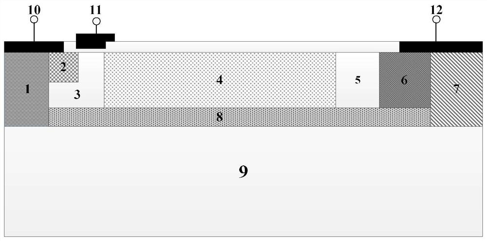
[0044] Such as figure 1 As shown, this embodiment proposes a substrate-integrated anti-parallel freewheeling diode RC-LIGBT device, which includes: P+ emitter 1, N+ electron emitter 2, P-body3, N-type drift region 4, buffer Layer 5, P-type collector 6, N-type collector 7, silicon dioxide insulating layer 8, P-type substrate 9, emitter 10, gate 11 and collector 12.

[0045] The RC-LIGBT device is divided into an IGBT conductive region and a PIN diode region from top to bottom, and the IGBT conductive region and the PIN diode region are separated by a silicon dioxide insulating layer 8 . Wherein, the conductive region of the IGBT is formed by setting a P+ emitter 1, an N+ electron emitter 2, a P-body 3, an N-type drift region 4, a buffer layer 5, and a P-type collector 6. The PIN diode region is formed by a P+ emitter 1 , a P-type substrate 9 and an N-type collector 7 . The upper side of the silicon dioxide insulating layer 8 is closely connected with the lower side of the P-b...

Embodiment 2

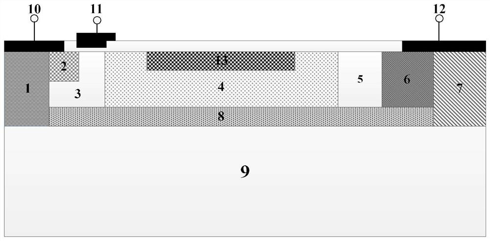
[0049] Such as figure 2 As shown, a preferred RC-LIGBT device with substrate integrated anti-parallel freewheeling diode in the embodiment of the present invention can be further expanded and applied to RESURF theory and structure. figure 2 Including P+ emitter 1, N+ electron emitter 2, P-body 3, N-type drift region 4, buffer layer 5, P-type collector 6, N-type collector 7, silicon dioxide insulating layer 8, P-type substrate 9. The emitter 10, gate 11, collector 12, and P-top 13 are Double RESURF structures.

[0050] The upper side of the P-top 13 area is flush with the upper side of the N-type drift region 4 , and the left, lower and right sides are completely covered by the N-type drift region 4 . The N-type drift region 4 has a length of 18 μm, a thickness of 4 μm, and a doping concentration of 1×10 15 cm -3 . The P+ emitter 1 and the N+ electron emitter 2 are located below the emitter 10 , the left side of the N+ electron emitter 2 is completely covered by the P+ em...

Embodiment 3

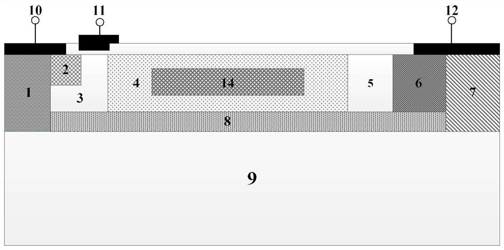
[0053] Such as image 3 As shown, a preferred substrate-integrated anti-parallel freewheeling diode RC-LIGBT device in the embodiment of the present invention includes a P+ emitter 1, an N+ electron emitter 2, a P-body 3, an N-type drift region 4, and a buffer layer 5. P-type collector 6, N-type collector 7, silicon dioxide insulating layer 8, P-type substrate 9, emitter 10, gate 11, collector 12, P-type 14.

[0054] The P-type 14 region is completely covered by the N-type drift region 4 . The N-type drift region 4 has a length of 18 μm, a thickness of 4 μm, and a doping concentration of 1×10 15 cm -3 . The P+ emitter 1 and the N+ electron emitter 2 are located below the emitter 10 , the left side of the N+ electron emitter 2 is completely covered by the P+ emitter 1 , and the bottom and right sides are completely covered by the P-body 3 . The right side of the P-body 3 is next to the left side of the N-type drift region 4, the right side of the N-type drift region 4 is ne...


PUM

PropertyMeasurementUnit
lengthaaaaaaaaaa
thicknessaaaaaaaaaa
thicknessaaaaaaaaaa

Abstract

The invention relates to an RC-LIGBT device with a substrate integrated with an anti-parallel fly-wheel diode, and belongs to the technical field of power semiconductors. The device comprises an IGBT conductive region formed by a P + emitter, an N + electron emitter, a P-body, an N-type drift region, a buffer layer and a P-type collector electrode, and a PIN freewheeling diode conductive region formed by the P + emitter, a P-type substrate and an N-type collector electrode, wherein during positive conduction, the IGBT conductive region works, no negative resistance effect exists, and the conduction voltage is reduced, and during reverse conduction, the PIN freewheeling diode conductive region works, and a hole current path is provided to realize integration of the diode. According to the invention, the negative resistance Snapback effect of a traditional RC-LIGBT is eliminated while the turn-off loss can be greatly reduced.

Description

technical field [0001] The invention belongs to the technical field of power semiconductors and relates to an RC-LIGBT device with a substrate integrated anti-parallel freewheeling diode. Background technique [0002] Insulated Gate Bipolar Transistor (IGBT) is a bipolar semiconductor power device that combines MOSFET and BJT. It has the advantages of reduced conduction voltage, low driving power consumption and high operating frequency, and is widely used. Used in communication technology, new energy equipment and various consumer electronics fields, it is the core device of electronic power system. Among them, the Lateral Insulated Gate Bipolar Transistor (LIGBT) is easy to integrate on the Si base, and is usually used in SOI-based power smart systems, and is a typical representative of bipolar semiconductor devices. [0003] However, since the LIGBT does not have reverse conduction capability, it is usually necessary to connect a reverse freewheeling diode in parallel ne...

Claims


Application Information

Patent Timeline
Patent Type & Authority Applications(China)
IPC IPC(8): H01L29/06H01L29/739
CPCH01L29/0603H01L29/7393Y02B70/10
Inventor 陈伟中林徐葳秦海峰黄义
Owner CHONGQING UNIV OF POSTS & TELECOMM
Why Eureka
Try Eureka