Inter-chip conductive bridge structure and manufacturing method thereof

A manufacturing method and conductive bridge technology, applied in the direction of microstructure technology, microstructure devices, manufacturing microstructure devices, etc., can solve the problems of conductive bridge short circuit, photoresist missing shape, photoresist deformation, etc., to avoid short circuit or open circuit, improve test efficiency, and reduce misjudgment

Pending Publication Date: 2021-12-17
深圳市德金元科技有限公司
View PDF0 Cites 1 Cited by
  • Summary
  • Abstract
  • Description
  • Claims
  • Application Information

AI Technical Summary

Problems solved by technology

[0005] However, due to the photolithography and etching of some film layers (including dielectric layer, conductive layer, etc.) The coated photoresist is easy to be thrown out above the top surface of the layer structure and is difficult to stay, and it is easy to appear photolithography above the top surface of the layer structure after development. The glue is missing or the morphology is not good. For example, the photoresist that should have stayed on the top surface of the layered structure rides on the sidewall of the layered structure, causing the problem of deformation of the photoresist after development, while the photoresist above the top surface of the layered structure The lack of glue can easily cause the conductive layer in the final conductive bridge to be disconnected at some positions, thereby causing the problem of conductive bridge disconnection. The poor morphology of the photoresist can easily cause the conductive layer in the layer structure to be short-circuited, thereby causing the conductive bridge to short-circuit The problem of chip testing caused misjudgment, which affected the accuracy of test results and was not conducive to the further improvement of test efficiency.

Method used


Image

  • Inter-chip conductive bridge structure and manufacturing method thereof
  • Inter-chip conductive bridge structure and manufacturing method thereof
  • Inter-chip conductive bridge structure and manufacturing method thereof

Examples


Embodiment Construction

[0044] In the following description, numerous specific details are given in order to provide a more thorough understanding of the invention, however, it will be apparent to those skilled in the art that the invention may be practiced without one or more of these details.

[0045] In other examples, in order to avoid confusion with the present invention, some technical features known in the art are not described. It should be understood that the present invention can be implemented in different forms and should not be construed as being limited to the implementations set forth herein. Rather, these embodiments are provided so that this disclosure will be thorough and complete, and will fully convey the scope of the invention to those skilled in the art.

[0046] In the drawings, the size and relative sizes of layers and regions may be exaggerated for clarity, and like reference numerals designate like elements throughout.

[0047] It should be noted that if there is a directional...


PUM


Abstract

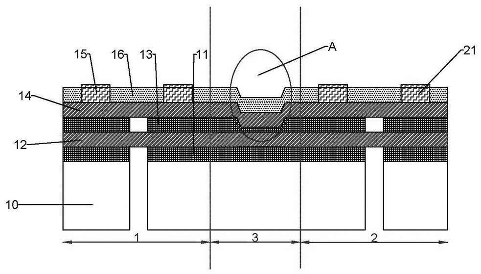
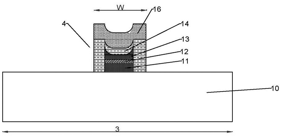
The invention discloses an inter-chip conductive bridge structure and a manufacturing method thereof. An opening can be etched in at least one of a to-be-etched layer and a layer structure in a bridging area, a curved surface is arranged below the opening, the curved surface at least comprises a pair of surfaces with two non-right-angle adjacent edges, preferably, the curved surface is a surface with fillets, the opening can prevent the photoresist in the opening from being thrown out, and when the photoresist is coated and developed, the opening can ensure that the photoresist on the top surface of the layer structure is effectively reserved with proper thickness and width and better morphology, so that when the photoresist layer is used as a mask to etch the layer to be etched to form a conductive bridge, the photoresist can effectively protect the layer structure and the to-be-etched layer on the top surface of the layer structure, so that the required shape and width of the conductive bridge are achieved, the performance is reliable, short circuit or open circuit of the formed conductive bridge is avoided, and the product manufacturing yield and the test accuracy are further improved.

Description

technical field [0001] The invention relates to the field of integrated circuit manufacturing and semiconductor technology, in particular to a conductive bridge structure between chips and a manufacturing method. Background technique [0002] The chip can also combine multiple logic components, analog components, active components, and passive components, micro-electromechanical systems (MEMS), optical components and other components into one unit to form a chip that can provide multiple functions. The system or subsystem of different ICs can be integrated to realize a more complex system, so that the chip size under the same function is smaller, the design cycle and market cycle are shorter, and the cost is lower. [0003] Wafer-level system chip packaging is to complete the packaging integration process on the substrate. It has the advantages of greatly reducing the area of ​​the packaging structure, reducing manufacturing costs, optimizing electrical performance, and batc...

Claims


Application Information

Patent Timeline
Patent Type & Authority Applications(China)
IPC IPC(8): B81B7/00B81B7/02B81C1/00
CPCB81B7/0006B81B7/02B81C1/00095B81C1/00404
Inventor 黄俊凯余玄黄静梅
Owner 深圳市德金元科技有限公司
Why Eureka
Try Eureka